Hammer drill and /or percussion hammer with no-load operation control that depends on application pressure

a technology of operation control and hammer drill, which is applied in the direction of portable power-driven tools, percussive tools, bulkheads/piles, etc., can solve the problems of preventing the rapid creation of a stabilizing centering, the danger of hammer damage to the operator or to the operator, and the inability to avoid unplanned jumping away

Inactive Publication Date: 2005-07-05
WACKER NEUSON SE
View PDF21 Cites 51 Cited by
  • Summary
  • Abstract
  • Description
  • Claims
  • Application Information

AI Technical Summary

Benefits of technology

[0013]The underlying object of the present invention is to indicate a hammer drill and / or percussion hammer in which, when the hammer is pressed against the stone to be worked, an appropriate circuit ensures a reliable change between no-load and percussion operation, without excessive increase in the pressure force that is to be applied by the operator.

Problems solved by technology

However, because air spring hammer mechanisms having a simple design have a tendency to begin percussion operation suddenly, the undesired jumping away cannot always be avoided.
In the processing of edges, there is even the danger of damage to the hammer or to the operator himself, if the chisel jumps into the air from the edge.
However, this has the disadvantage that the characteristic of the motor speed is always the same when accelerating from no-load operation to percussion operation, while the particular case of application requires a specifically adapted run-up.
In addition, the lowering of the motor speed prevents the rapid creation of a stabilizing centering in the material that is to be worked.
However, sleeve controlling also has a disadvantage.
Especially in heavy hammers, this is disadvantageous because the spring acting on the control sleeve must be designed such that it has to support at least the weight of the tool on the one hand, or the weight of the hammer on the other hand, in order to avoid an undesired change from no-load operation to percussion operation.
If work is to be carried out with the hammer oriented upward, this means that even in no-load operation the entire weight of the tool lies against the control sleeve, and thus against the spring, so that the spring has to hold the tool.

Method used


Image

  • Hammer drill and /or percussion hammer with no-load operation control that depends on application pressure
  • Hammer drill and /or percussion hammer with no-load operation control that depends on application pressure
  • Hammer drill and /or percussion hammer with no-load operation control that depends on application pressure

Examples


Embodiment Construction

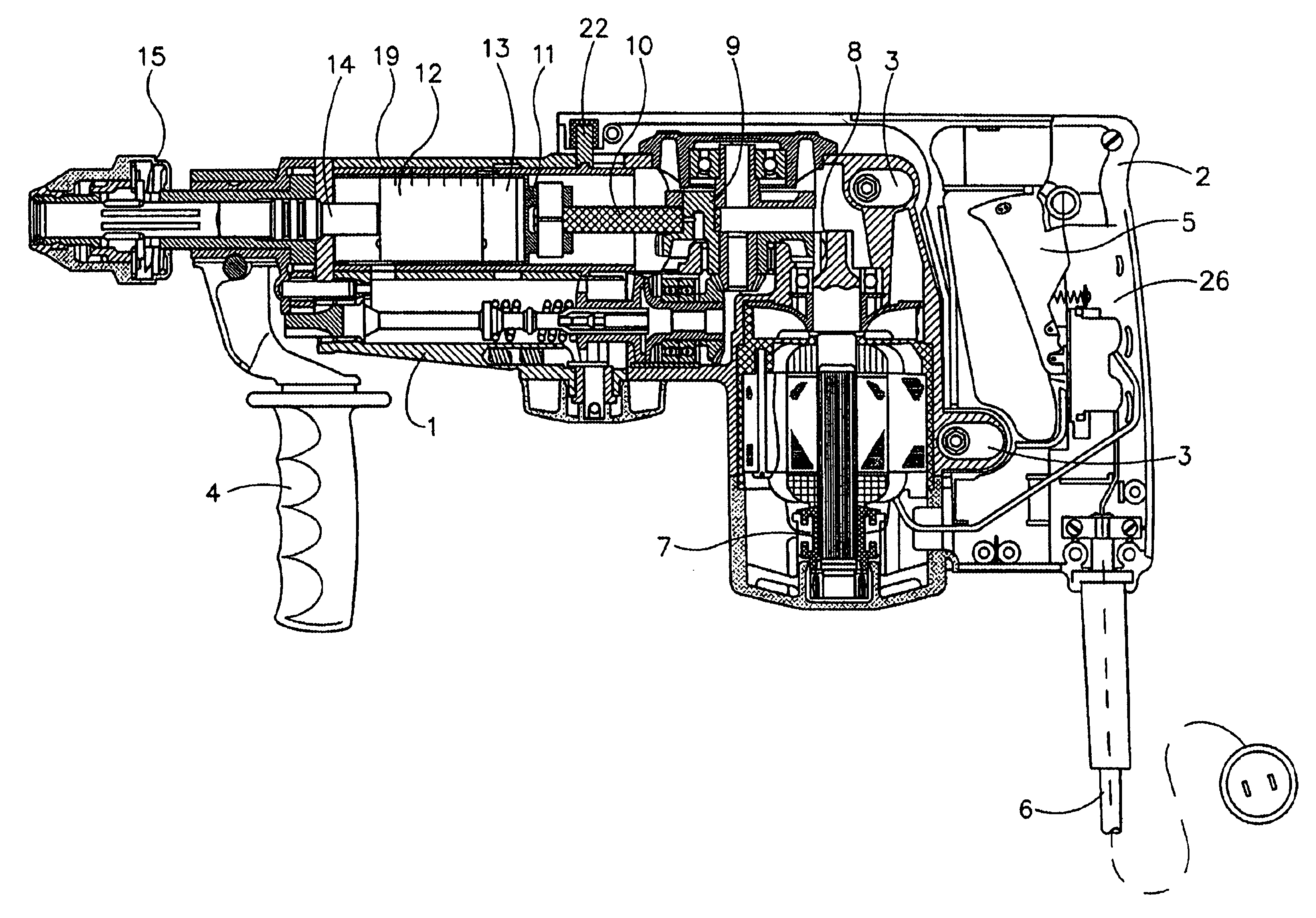
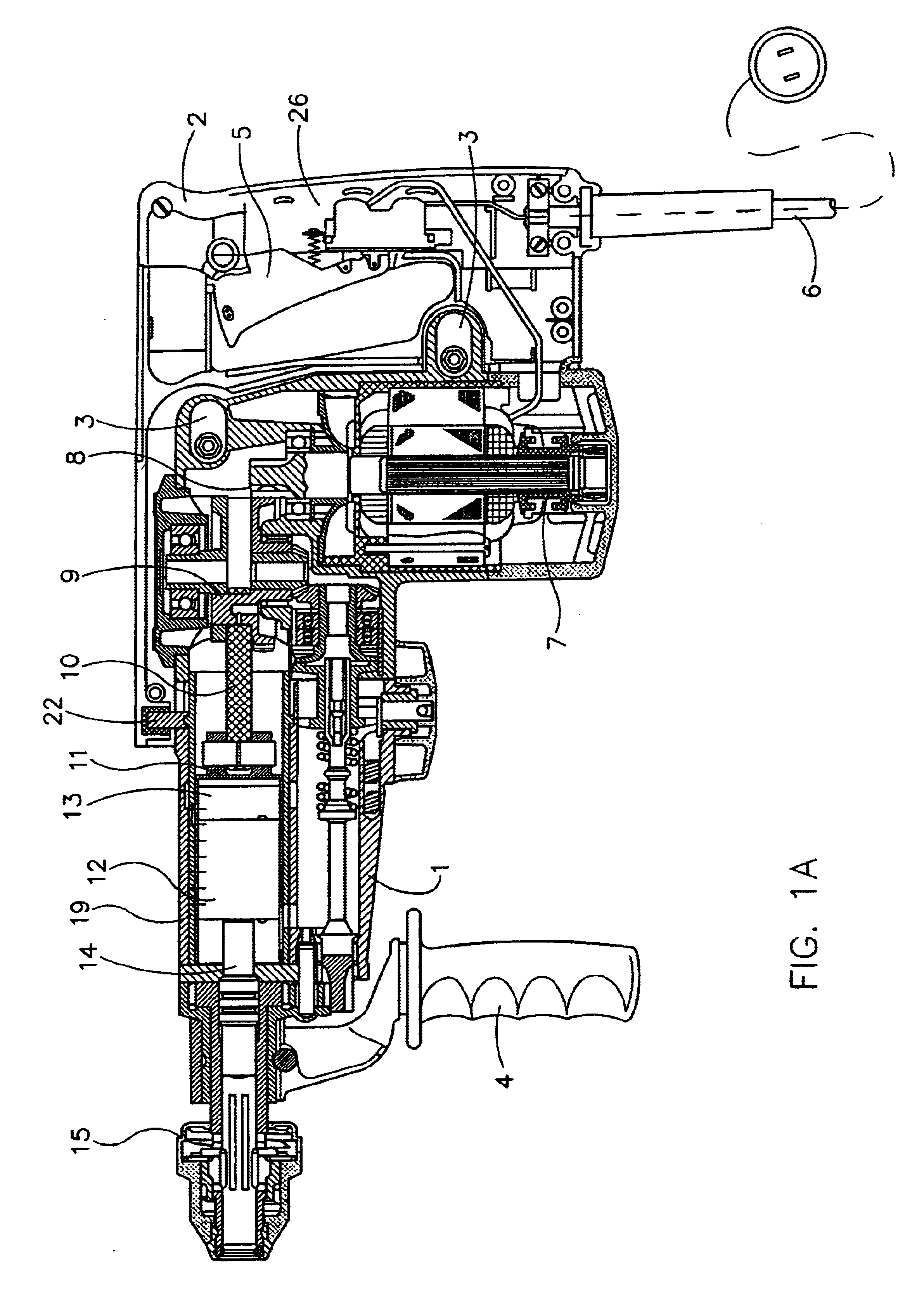
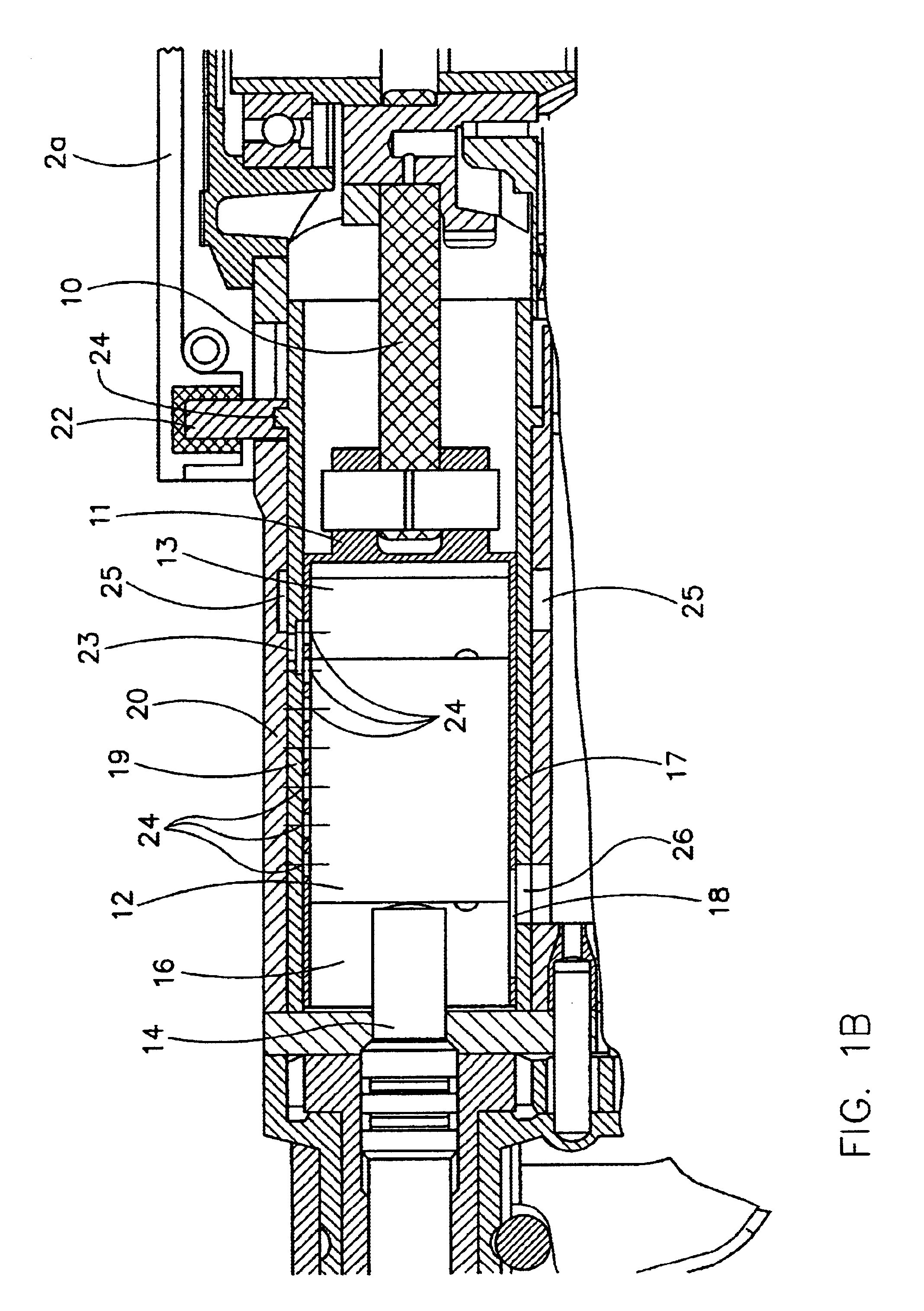
[0039]FIGS. 1A to 3B show the hammer according to a first specific embodiment in different operating states and different detail enlargements. The hammer according to the second specific embodiment is shown in FIGS. 4 to 5B. First, the hammer according to the first specific embodiment is described on the basis of FIGS. 1A and 1B.

[0040]On a hammer housing 1, a handle 2 is attached so as to be capable of axial displacement via spring systems 3. On the front end of hammer housing 1, an additional handle 4 is fastened, which however is not important for the present invention and serves only for the improved guiding of the hammer.

[0041]Spring system 3 can be for example an anti-vibration system for mitigating the vibrations and impacts—acting on handle 2 and produced by the air spring hammer mechanism or by the action of the tool—on handle 2, and thus on the operator's hand, which grasps handle 2 at a grasping point 2b. To the extent that such an anti-vibration system is already provided...


PUM

PropertyMeasurementUnit
pressureaaaaaaaaaa
pressure forceaaaaaaaaaa
spring forceaaaaaaaaaa

Abstract

A percussion hammer drill and/or percussion hammer that can be guided by a handgrip comprises a pneumatic spring striking mechanism with a reciprocating drive piston and with a percussion piston that can be operated by the drive piston. A cavity for accommodating a pneumatic spring is provided between the drive piston and the percussion piston. The cavity can be connected to the surrounding area via a no-load operation channel in order to achieve a no-load operation. This this end, a valve is situated inside the no-load operation channel and can be controlled according to an application force that can be applied to the handgrip by the operator.

Description

BACKGROUND OF THE INVENTION[0001]1. Field of the Invention[0002]The present invention relates to a hammer drill and / or percussion hammer according to the preamble of patent claim 1.[0003]2. Description of the Related Art[0004]A hammer drill and / or percussion hammer, designated “hammer” in the following, standardly has an air pneumatic spring hammer mechanism in which a drive plunger is set into an oscillating back-and-forth movement by an electric motor, using a crankshaft or wobble shaft drive. A percussion piston is situated before the drive piston, so that a hollow space, in which an air spring can form, is present between the drive piston and the percussion piston. The air spring transmits the back and forth movement of the drive piston to the percussion piston, and drives this percussion piston against the shaft of a tool or against an intermediately connected rivet header. Hammers of this sort are known in many different specific embodiments.[0005]In the use of the hammer for ...

Claims


Application Information

Patent Timeline
Patent Type & Authority Patents(United States)
IPC IPC(8): B25D11/00B25D16/00B25D17/04B25D17/00B23B45/16B25F5/00
CPCB25D11/005B25D16/00B25D17/043B25D2211/003B25D2211/068B25D2250/035B25D2250/131B25D2250/221
Inventor BERGER, RUDOLF
Owner WACKER NEUSON SE
Why Eureka
Try Eureka