Variable valve timing system and method for controlling the same

Active Publication Date: 2009-04-23
TOYOTA JIDOSHA KK +1
View PDF1 Cites 8 Cited by
  • Summary
  • Abstract
  • Description
  • Claims
  • Application Information

AI Technical Summary

Benefits of technology

[0008]The invention provides a variable valve timing system that reliably changes the valve timing by a required amount after an engine stop command is issued, and that accurately sets the valve timing when the engine is stopped to the valve timing at the target phase, and a method for controlling the same.

Problems solved by technology

Such inconvenience is caused because the hydraulic pressure used to drive the camshaft is insufficient or the response of the camshaft to the hydraulic control is slow in such occasions.

Method used


Image

  • Variable valve timing system and method for controlling the same
  • Variable valve timing system and method for controlling the same
  • Variable valve timing system and method for controlling the same

Examples


Embodiment Construction

[0044]Hereafter, an embodiment of the invention will be described with reference to the accompanying drawings. In the following description, the same or corresponding elements will be denoted by the same reference numerals. The names and functions of the elements having the same reference numerals are also the same. Accordingly, the descriptions concerning the elements having the same reference numerals will be provided only once below.

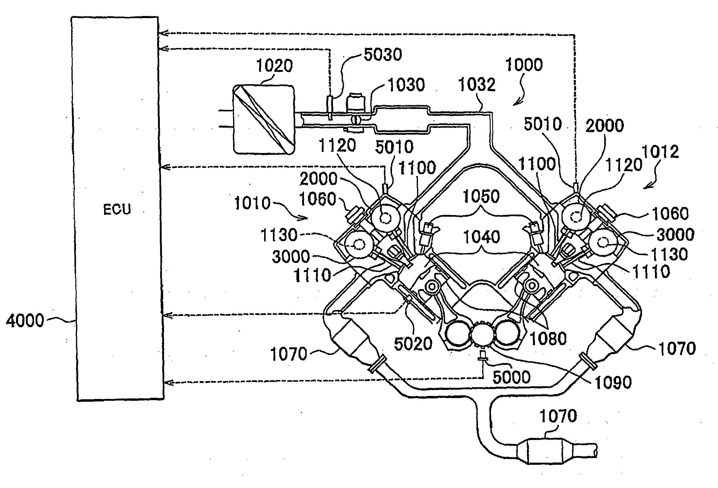
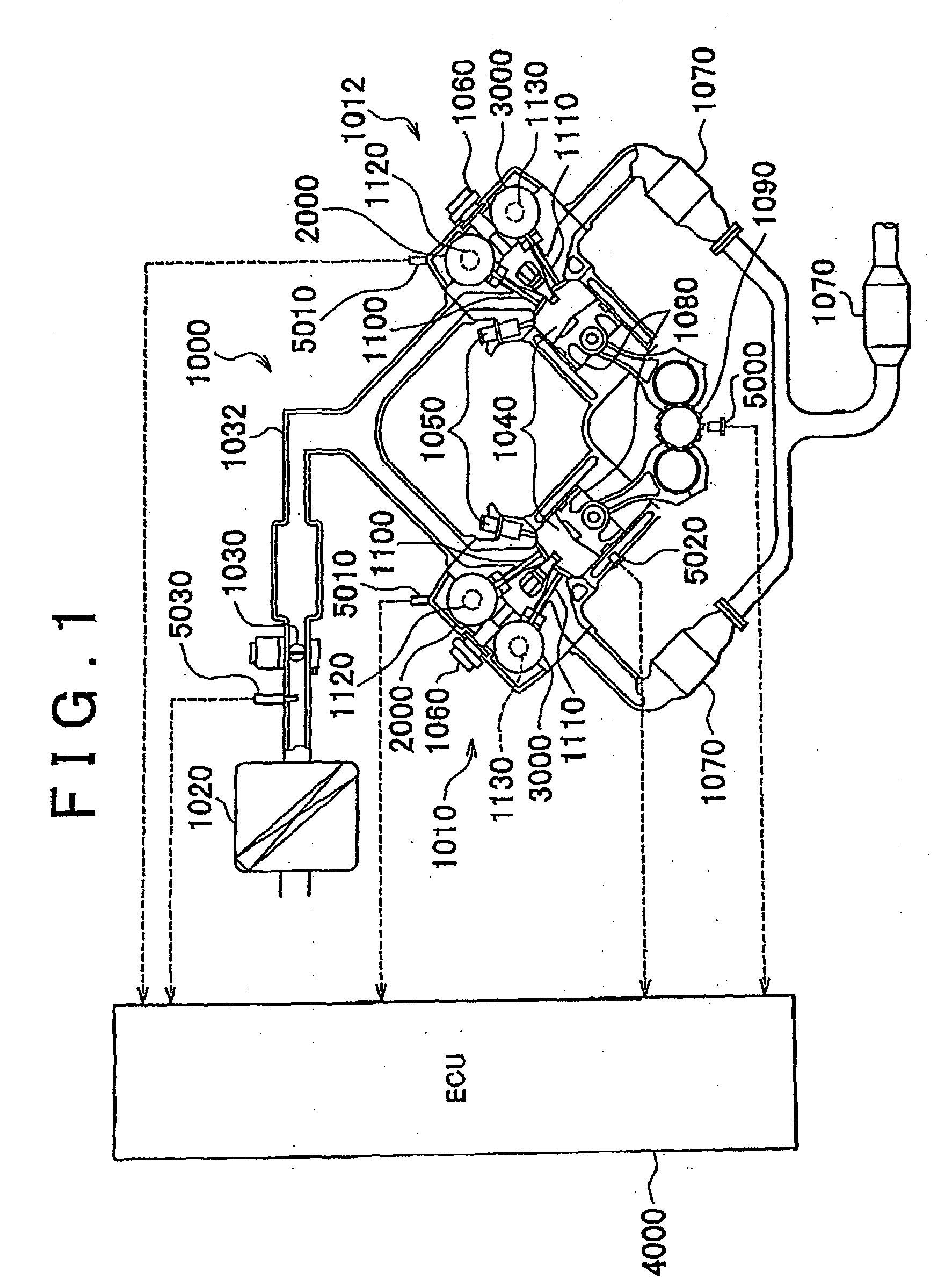
[0045]First, a vehicle engine provided with a variable valve timing system according to the embodiment of the invention will be described with reference to FIG. 1.

[0046]An engine 1000 is an eight-cylinder V-type engine including a first bank 1010 and a second bank 1012 each of which has four cylinders therein. Note that, the variable valve timing system according to the embodiment of the invention may be applied to any types of engines. Namely, the variable valve timing system may be applied to engines other than an eight-cylinder V-type engine.

[0047]...


PUM


Abstract

In an intake valve phase control after an engine stop command is issued, a stop-time phase is used as a target value. In the intake valve phase control, when the mode changeover condition is not satisfied, and an electric motor that serves as an actuator is not in a locked-state, the highest-speed mode, in which the amount of electric power supplied to the electric motor is fixed to the maximum value, is selected to reliably change the intake valve phase by a required amount. Then, the intake valve phase comes close to the stop-time phase and the mode changeover condition is satisfied, the control mode is changed from the highest-speed mode to the normal mode to set the control phase to the stop-time phase with higher accuracy, and the feedback control over the intake valve phase is executed.

Description

BACKGROUND OF THE INVENTION[0001]1. Field of the Invention[0002]The invention relates generally to a variable valve timing system and a method for controlling the same, and, more specifically, to a variable valve timing system that uses an electric motor as an actuator and a method for controlling the same.[0003]2. Description of the Related Art[0004]A variable valve timing (VVT) system that changes the phase (i.e., crank angle), at which an intake valve or an exhaust valve is opened / closed, based on the engine operating state has been used. Such variable valve timing system changes the phase of the intake valve or the exhaust valve by rotating a camshaft, which opens / closes the intake valve or the exhaust valve, relative to, for example, a sprocket. The camshaft is rotated hydraulically or by means of an actuator, for example, an electric motor.[0005]With a variable valve timing system that hydraulically drives a camshaft, the variable valve timing control is sometimes not executed...

Claims


Application Information

Patent Timeline
IPC IPC(8): F01L1/34
CPCF01L1/344F01L1/352F01L2001/0537Y02T10/18F01L2820/032F02D13/0219F01L2800/03Y02T10/12
Inventor INOUE, YASUMICHIHATTORI, MASAYOSHIABE, TSUKASAYAMAMOTO, KENJI
Owner TOYOTA JIDOSHA KK
Why Eureka
Try Eureka