
Compressor for a refrigerating plant and refrigerating plant comprising said compressor

Active Publication Date: 2016-03-03
FRASCOLD
View PDF32 Cites 1 Cited by
  • Summary
  • Abstract
  • Description
  • Claims
  • Application Information

AI Technical Summary

Benefits of technology

The present invention aims to manufacture a compressor that overcomes the shortcomings of prior art. Specifically, it aims to create a compressor that is reliable, easy to adjust the refrigerating capacity based on the thermal load, and is both cost-effective and simple in construction.

Problems solved by technology

In fact, it often occurs that the refrigerating capacity of the compressor is excessive compared to the required thermal load.
For example, the excessive refrigeration may lead to the formation of ice on the evaporator and determine a lowering of the dew point of the evaporator.
The lowering of the dew point may cause an excessive dehumidification of the processed air, creating uncomfortable conditions if the compressor supplies an air-conditioning system, or may cause a significant weight drop of the product stored if the compressor supplies a refrigerating room.
Such solution, however, risks to dangerously increase the number of start-ups per hour of the compressor and significantly reduce the operating life of the compressor.
However, such solution, besides having a high starting cost and a more complicated control system, does not overcome the disadvantage of having to frequently restart the compressors to face the thermal load variation.
This type of regulation is too rough and is not sufficient to optimize the performance and efficiency of the plant upon variation of the required thermal load.
However, such solution proved to be not very efficient in that it determines a continuous fluctuation of pressures and temperatures inside the compressor, subjecting the inner parts of the compressor to dangerous stresses.
Therefore, such solution is not reliable and requires constant monitoring of the operating conditions of the compressor.

Method used


Image

  • Compressor for a refrigerating plant and refrigerating plant comprising said compressor
  • Compressor for a refrigerating plant and refrigerating plant comprising said compressor
  • Compressor for a refrigerating plant and refrigerating plant comprising said compressor

Examples


Embodiment Construction

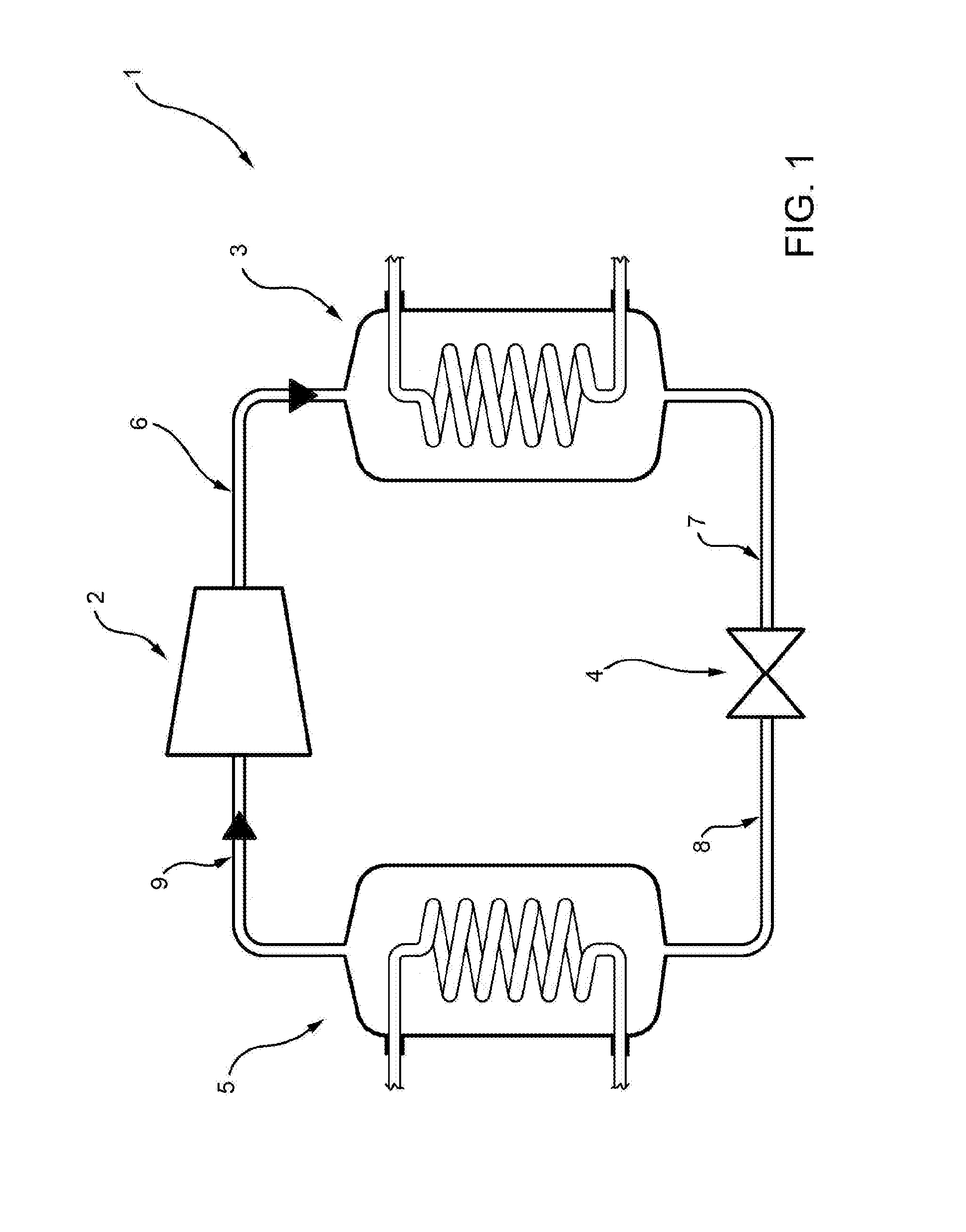
[0026]In FIG. 1, reference numeral 1 indicates a refrigerating plant wherein a refrigerating fluid flows.

[0027]Refrigerating fluid means a refrigerating substance which may take the liquid or gaseous state inside the plant 1 depending on the pressure and temperature conditions to which it is subjected.

[0028]The refrigerating fluid is, for example, a fluid selected from the group consisting of HCFC, HFC, HFO, CO2, HC.

[0029]The plant 1 comprises a compressor 2, a condenser 3, an expansion valve 4 and an evaporator 5.

[0030]A high-pressure delivery line 6 supplies the condenser 3 with the refrigerating fluid compressed by the compressor 2. In particular, the refrigerating fluid supplied to the condenser 3 is in the form of vapour.

[0031]In the condenser 3 the refrigerating fluid in the form of vapour is transformed to the liquid form.

[0032]A high-pressure line 7 supplies the refrigerating fluid output from the condenser 3 to the expansion valve 4, where the pressure of the refrigerating ...


PUM


Abstract

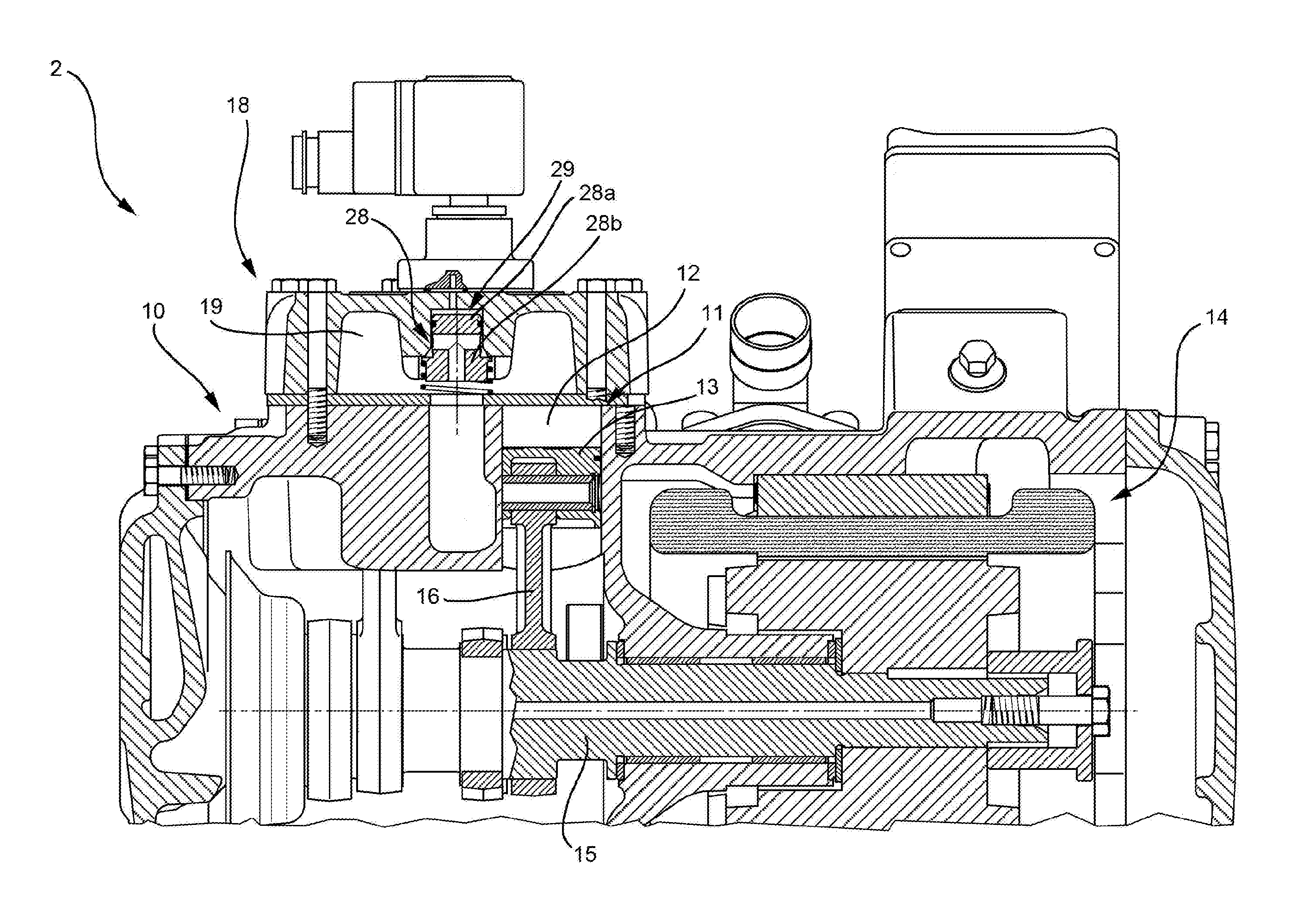
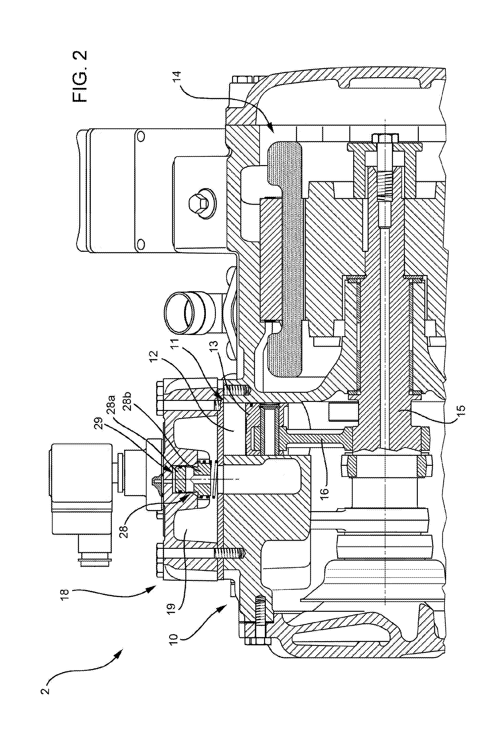
A compressor for a refrigerating plant comprising at least one cylinder (12); at least one piston (13), which slides alternately inside the cylinder (12); at least one head (18a) provided with a suction chamber (19), connected to a suction line (9) of the plant (1) and to the cylinder (12) to supply the cylinder (12) with a refrigerating fluid, and with a suction valve (25a), configured to regulate the flow rate of refrigerating fluid; the suction valve (25a) is movable between a first position, wherein is defined a first flow area which allows the suction of a first flow rate of refrigerating fluid, and a second position wherein is defined a second flow area smaller than the first flow area which allows the suction of a second flow rate of refrigerating fluid lower than the first flow rate.

Description

TECHNICAL FIELD[0001]The present invention relates to a compressor for a refrigerating plant and a refrigerating plant comprising said compressor.BACKGROUND ART[0002]In the field of refrigerating plants there has always been a need for regulating the refrigerating capacity of the compressor based on the actual thermal load required. In fact, it often occurs that the refrigerating capacity of the compressor is excessive compared to the required thermal load. Such situation occurs, for example, in supermarket refrigerating plants or refrigerating rooms during night hours. The thermal load required overnight is, in fact, definitely lower than the thermal load required during daily hours, wherein operations of massive removal of food from refrigerating rooms, opening of freezer doors in a crowded place, etc. occur.[0003]If the refrigerating capacity of the compressor is constant, during night hours the compressor is capable of bringing the environment to the desired temperature in a sho...

Claims


Application Information

Patent Timeline
IPC IPC(8): F25B49/02F25B1/02
CPCF25B41/043F25B2400/074F25B1/02F25B49/022F25B2600/0272F25B41/22F04B39/06F04B49/22F04B49/225
Inventor BROGLIA, THOMAS
Owner FRASCOLD
Learn More