
Device for monitoring the voltage output by the cells of an electrochemical generator

a technology of electrochemical generators and devices, which is applied in the direction of electrochemical generators, instruments, material analysis, etc., can solve the problems of reversibly or irreversibly degrading or prematurely deteriorating all or some cells, premature ageing or even complete deterioration of one or more cells, and nearly complete discharge of this cell or eventually other cells, etc., to achieve the effect of simple implementation and reliable over tim

Active Publication Date: 2014-06-12
COMMISSARIAT A LENERGIE ATOMIQUE ET AUX ENERGIES ALTERNATIVES
View PDF4 Cites 12 Cited by
  • Summary
  • Abstract
  • Description
  • Claims
  • Application Information

AI Technical Summary

Benefits of technology

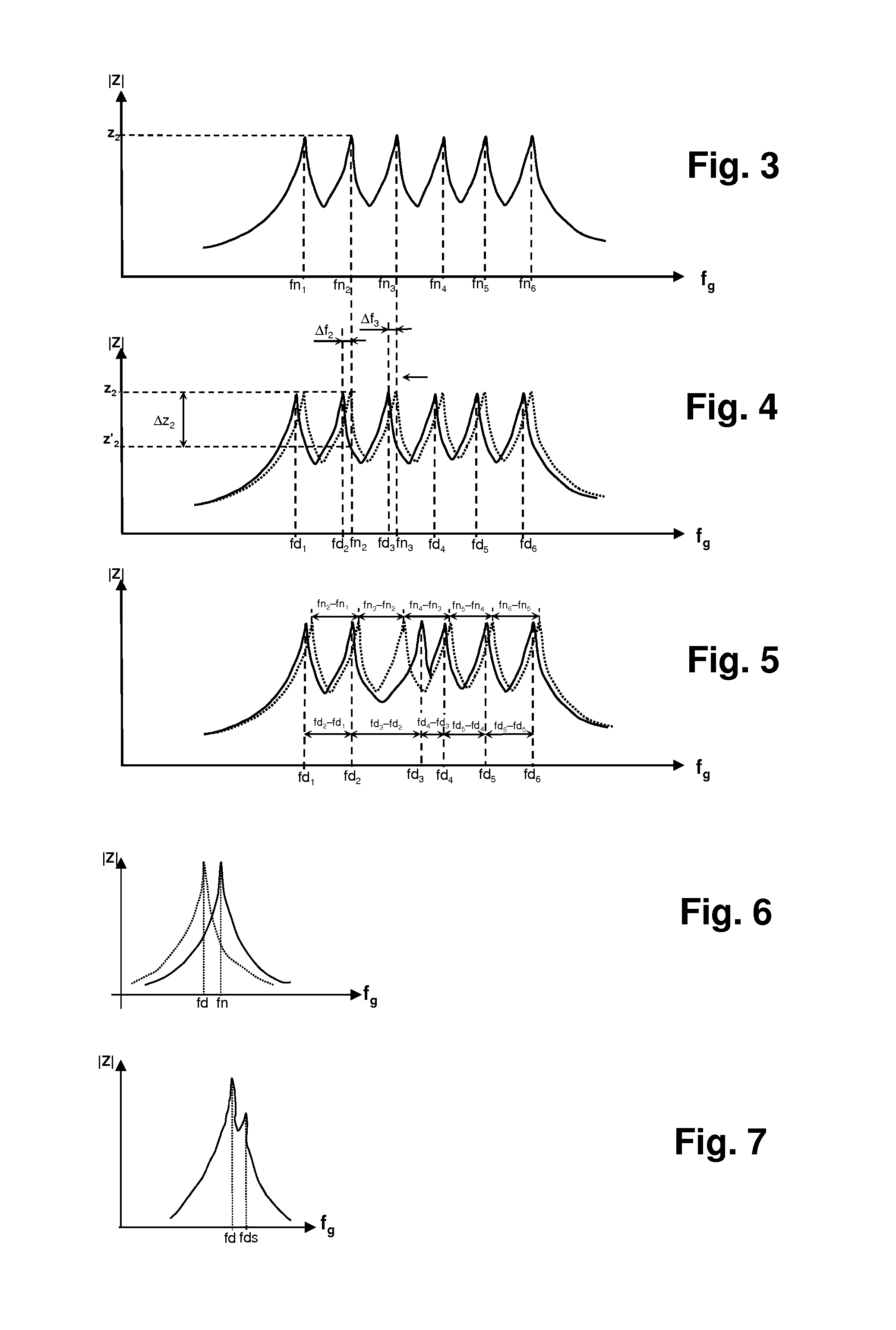
The invention provides an inexpensive and reliable solution for monitoring the state of cells in an electrochemical generator. The solution uses a resonant circuit with a reactive passive component that detects changes in DC voltage across its terminals. This transformation to the frequency domain simplifies connection and reduces risks of malfunction. The measurement is a passive measurement because it requires very little current. The resonant peaks detected in the signal across the terminals of the bank of resonant circuits correspond to the various cells in the stack, providing information on their state.

Problems solved by technology

Thus, it is necessary, in practice, to monitor the voltage delivered by each cell of an electrochemical generator since degradation of the performance of one cell in the stack will directly affect the performance of the generator, and may also reversibly or irreversibly degrade or prematurely deteriorate all or some of the cells.
However, some voltage variations are due to defects in certain cells, which, if no action is taken, may lead to premature ageing, or even complete deterioration, of one or more cells.
For example, when the state of charge of one battery cell is different to that of the other cells, it may lead to overcharging or to nearly complete discharge of this cell or eventually other cells, and to their premature ageing.
In another example, when one cell of the fuel-cell stack is subjected to a momentary perturbation, for example due to poor evacuation of the water generated by the electrochemical reaction, or to a lack of fuel or oxidant on catalyst sites, the voltage of the cell may temporarily decrease.
If it decreases below a characteristic voltage threshold, the cell may generate heat, which may deteriorate it irreversibly.
However, the compactness of these electrochemical generators is often such that the connection density therein is very high, which makes it difficult or even impractical to measure the voltages across the terminals of the cells.
In these solutions, because of the compactness of the generators, connection is a major technological difficulty.
Moreover, it may prove to be difficult to guarantee the quality of the electrical contacts over time, under the normal operating conditions of a mass-market or industrial appliance, and over the entire lifetime of the appliance.
These monitoring solutions are more particularly difficult to implement in generators, intended for power applications, that consist of many cells in a very compact stack, notably fuel-cell stacks: the risk of a short-circuit between two measurement wires, and the risk of a measurement wire disconnecting or breaking, being particularly high in such stacks.Solutions using a circuit, integrated into the generator, that comprises means for measuring voltage across the terminals of the cells, associated with contactless means for transmitting, via radio waves, measured information to external analyzing means.
These integrated solutions have the major drawback of generally being more expensive than wired solutions.
Moreover, these various solutions generally require a regulated voltage source, which may cause the cells of the generator to discharge nonuniformly.

Method used


Image

  • Device for monitoring the voltage output by the cells of an electrochemical generator
  • Device for monitoring the voltage output by the cells of an electrochemical generator
  • Device for monitoring the voltage output by the cells of an electrochemical generator

Examples


Embodiment Construction

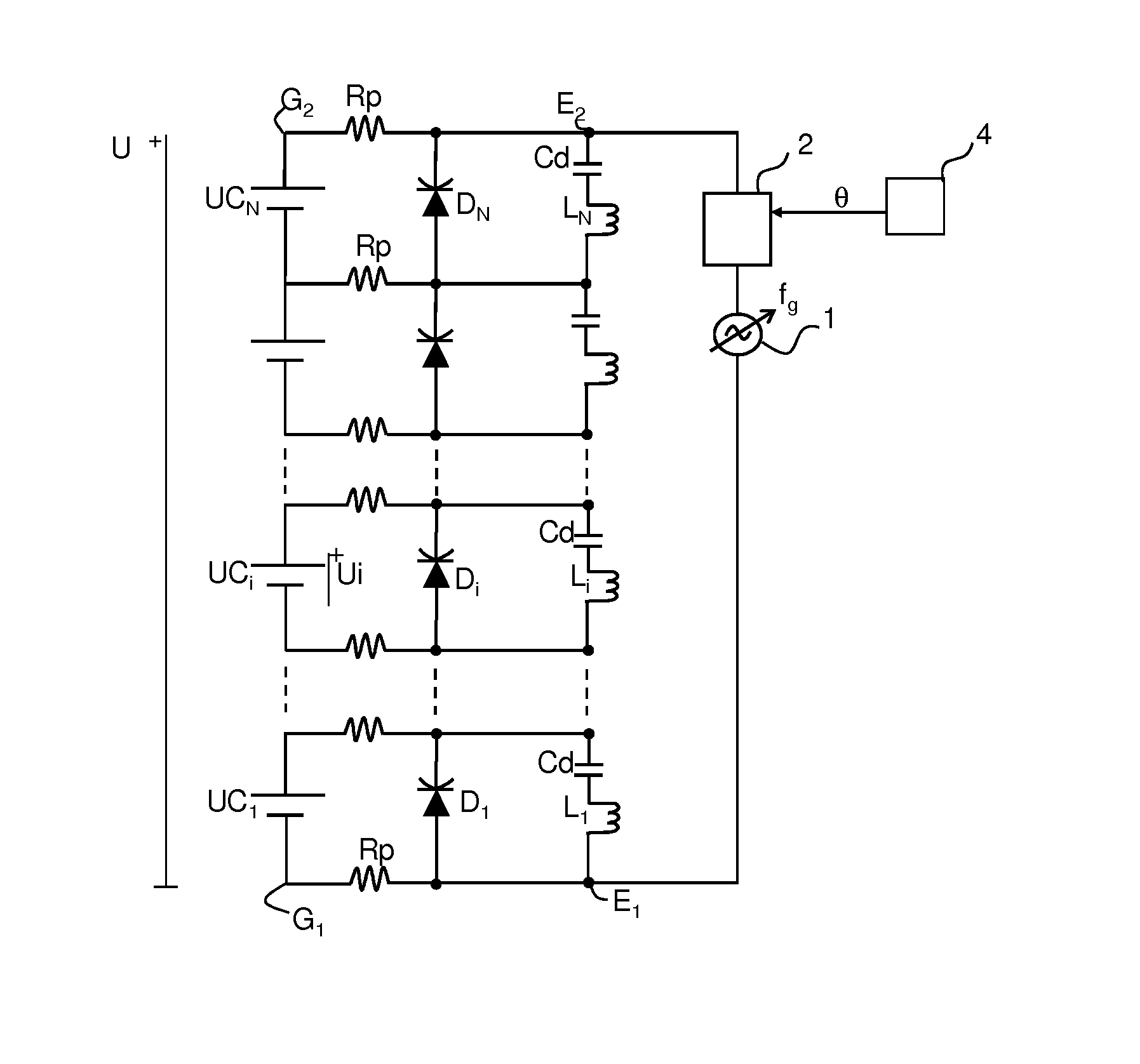
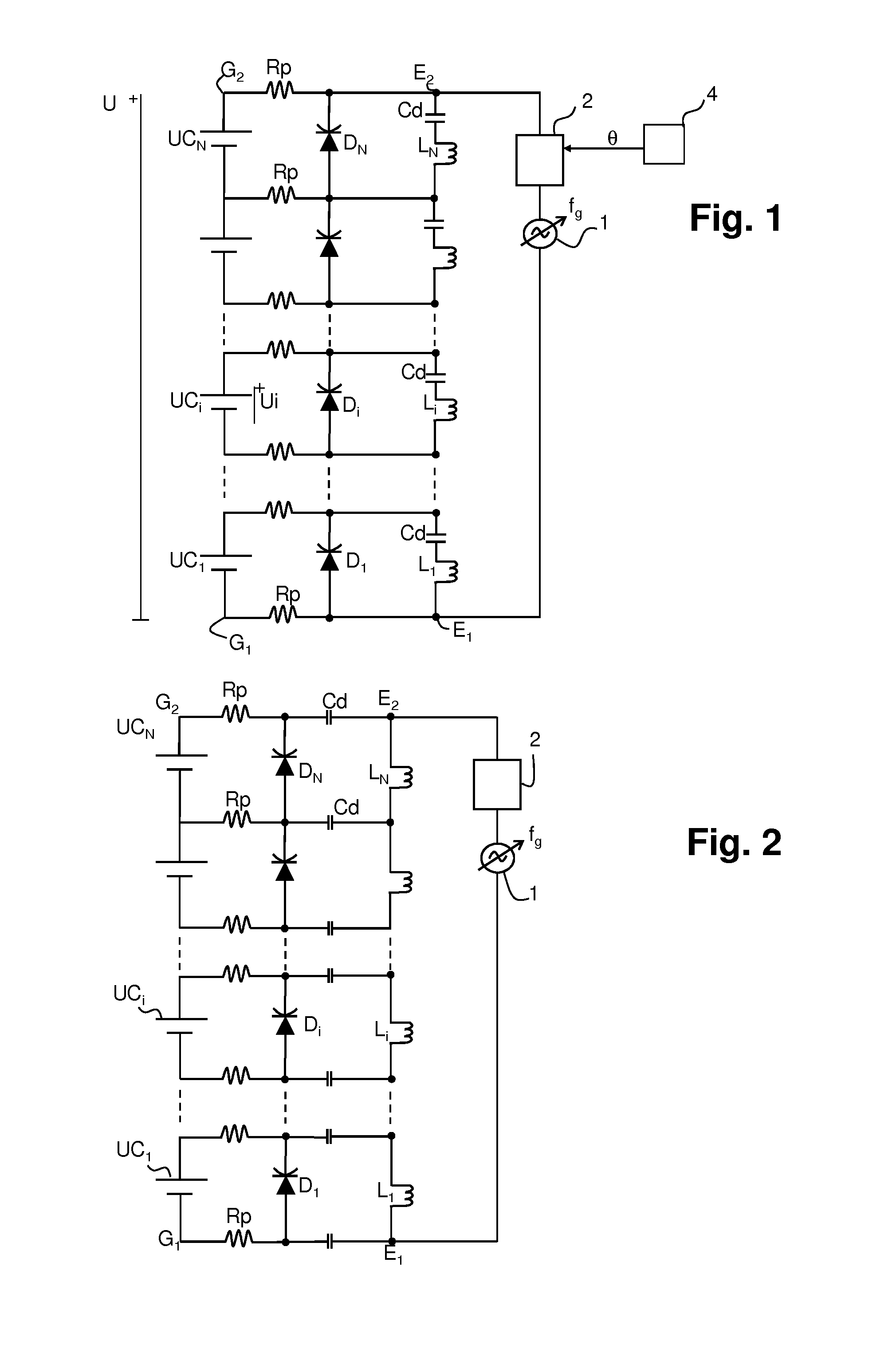
[0048]A first embodiment of a control circuit according to the invention is illustrated in FIG. 1, applied to a stack of N cells UC, of an electrochemical generator. Each cell UC, delivers, across its terminals, an elementary DC voltage Ui. Across the terminals G1, G2 of the stack a voltage U equal to the sum of the N elementary DC voltages Ui is obtained.

[0049]The control circuit comprises one resonant circuit per cell UCi. The resonant circuit comprises a first reactive passive component Di and a second reactive passive component Li, connected to the terminals of each cell UCi. The bank of resonant circuits are placed in series. The first reactive passive component is preferably a varicap diode, and the second reactive passive component an inductor. They are each connected in parallel to the cell UCi, as illustrated, forming a parallel LC resonant circuit with the capacitance Ci of the varicap diode and the inductance of the inductor Li. Since the cell UCi ensures the function of ...


PUM

PropertyMeasurementUnit
voltageaaaaaaaaaa
voltageaaaaaaaaaa
voltageaaaaaaaaaa

Abstract

An electrochemical generator comprises a stack of cells in series. To control the voltage across the terminals, controlling means comprise, for each cell, a first reactive passive component, the impedance varying depending on the DC voltage across its terminals, being biased by the voltage delivered by the cell, and a second reactive or resonant passive component forming, with the first reactive passive component, a series or parallel resonant circuit having a preset nominal resonant frequency for a nominal biasing voltage delivered by the cell. Using a variable frequency signal generator to supply the resonant circuits allows a detection circuit to detect resonant peak(s) across the terminals. The divergence between the resonant frequency corresponding to a detected peak and the nominal resonant frequency indicates the state of the associated cell. The frequency differences directly, for their part, provide information on the uniformity of the cells with respect to each other.

Description

TECHNICAL FIELD[0001]The invention relates to monitoring of the voltage delivered by the elementary cells of electrochemical generators, allowing their operating state to be controlled.PRIOR ART[0002]Electrochemical generators are conventionally made up of a stack of multiple cells in series. This is because an elementary cell cannot deliver an output voltage of a sufficient level to be exploitable as an energy source in an industrial or mass-market electrical appliance: a fuel cell is capable of providing a voltage comprised between 0.4 volts and 1.2 volts, depending on the nature of the cell, and notably depending on the fuel and oxidant used, and on the electrical current delivered, which depends mainly on the load; a battery cell is capable of delivering a voltage comprised between 1.2 volts and 3.8 volts, depending on the state of charge of the cell, on its temperature, and on the electrical current delivered.[0003]Stacking cells in series allows their outputs to be added to ob...

Claims


Application Information

Patent Timeline
Patent Type & Authority Applications(United States)
IPC IPC(8): G01R31/36H01M10/48H01M8/04
CPCG01R19/16542H01M8/0432H01M8/04552H01M10/482H01M10/486G01R31/392G01R31/396Y02E60/50Y02E60/10H01M8/04873G01R31/382
Inventor BUZON, DIDIERCHATROUX, DANIEL
Owner COMMISSARIAT A LENERGIE ATOMIQUE ET AUX ENERGIES ALTERNATIVES
Learn More