Microsensor produced in microsystem technologies for the measurement and/or detection of fouling

a microsystem technology and microsensor technology, applied in thermometers, instruments, material thermal analysis, etc., can solve the problems of affecting the performance of such installations, serious adverse effects on the progression of industrial processes, and intervention can represent tedious tasks for personnel, and achieve reliable measurements over time

Active Publication Date: 2014-06-10
AQUALABO SERVICES
View PDF18 Cites 12 Cited by
  • Summary
  • Abstract
  • Description
  • Claims
  • Application Information

AI Technical Summary

Benefits of technology

[0031]The applicant has realized that it would be advantageous to be able to have a new sensor for determination of fouling with a simplified concept that provides reliable measurements over time.

Problems solved by technology

In this exact case, the fouling of such installations can have adverse effects to the degree it is capable of affecting the performances of the installations (for example, the efficiency of an industrial process).
For whatever reason, the fouling irregularly causes a shutdown of the installation during a sometimes indeterminate interval; this has serious adverse effects on the progression of the industrial process.
These interventions can represent tedious tasks for personnel, the more so if the fouling has only been detected belatedly and if its thickness is too great.
This removal of fouling has a not inconsiderable economic cost since the cost of a temporary shutdown of operation should be included in the cost of maintenance operations.
It should likewise be noted that as the heat exchangers become fouled, there is a progressive loss of efficiency before a potential shutdown of operation of the installation or the part of the installation comprising these exchangers.
These latter measurements, however, present genuine problems to the degree in which:They do not allow local information to be obtained,They lack reactivity, but likewise sensitivity and extent of the measurement range.
This method and the associated system, however, have certain defects that limit their use in an industrial environment.
In particular, the presence of two points of physical attack on one pipe or a reactor always constitutes an installation constraint for a manufacturer, accompanied by a not inconsiderable cost.
Moreover, two temperature probes, even if they are of the same type, always have a certain drift of operation relative to one another due to, for example, variances that arise during their manufacture.
Moreover, the temperature probe that is used as a reference (the one that measures the fluid temperature) can itself become fouled; this introduces an additional drift relative to the other temperature probe.
This is because this significantly reduces the range of applications to the degree in which most industrial processes and / or water treatment processes continuously modify and perturb the average temperature of the environment.
Thus, this makes this method useless for continuous applications or for long-term operation (24 h / 24).
The defects that were just cited can thus lead to faulty measurements of fouling and thus to a lack of reliability of the method used.
Moreover, as a result of the operating mode and constituent elements of the physical device, the number of possible applications is limited.

Method used


Image

  • Microsensor produced in microsystem technologies for the measurement and/or detection of fouling
  • Microsensor produced in microsystem technologies for the measurement and/or detection of fouling
  • Microsensor produced in microsystem technologies for the measurement and/or detection of fouling

Examples


first embodiment

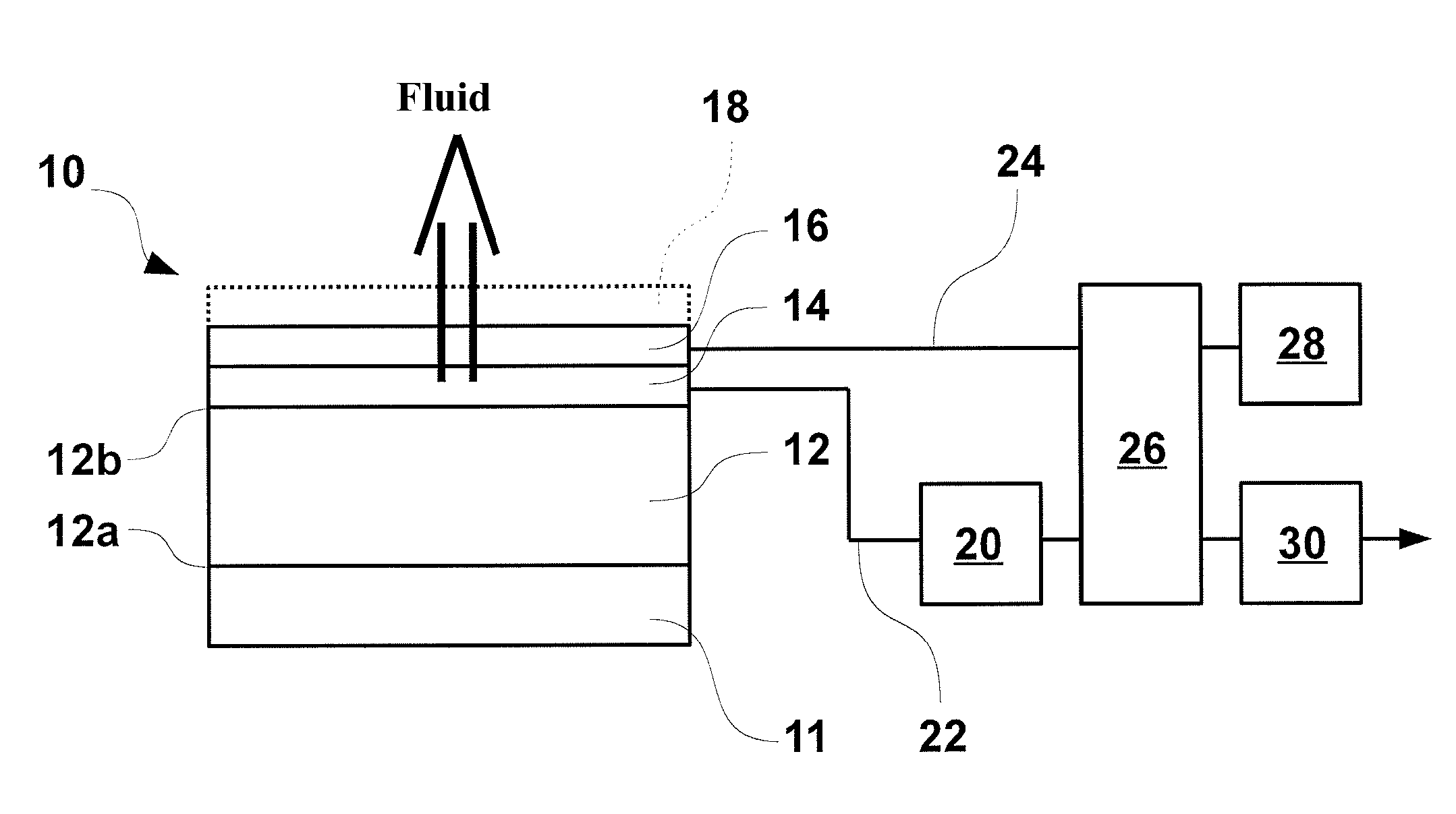
[0157]As shown schematically in FIG. 1a, a sensor 10 produced by using microsystem manufacturing technologies according to the invention comprises several operating elements assembled with one another on a substrate 12 with two opposite surfaces 12a, 12b, i.e.:[0158]At least one heating element 14 made in the form of a layer that is deposited on the surface 12b of the substrate 12 and that diffuses, on command, a monitored homogenous heat flow,[0159]At least one temperature measuring element 16 that is made in the form of a layer that is deposited on the layer 14 and that is located in such a way as to be in the most homogeneous part of the dissipated heat flow (when there is only one element 16 and it is at the center of the active zone of the heating element or elements),[0160]A heat insulator 11 in contact with the surface 12a of the substrate (the insulator is, for example, a Teflon block that is 400 μm thick with 0.25 W / mK of heat conductivity),[0161]And, optionally, at least o...

second embodiment

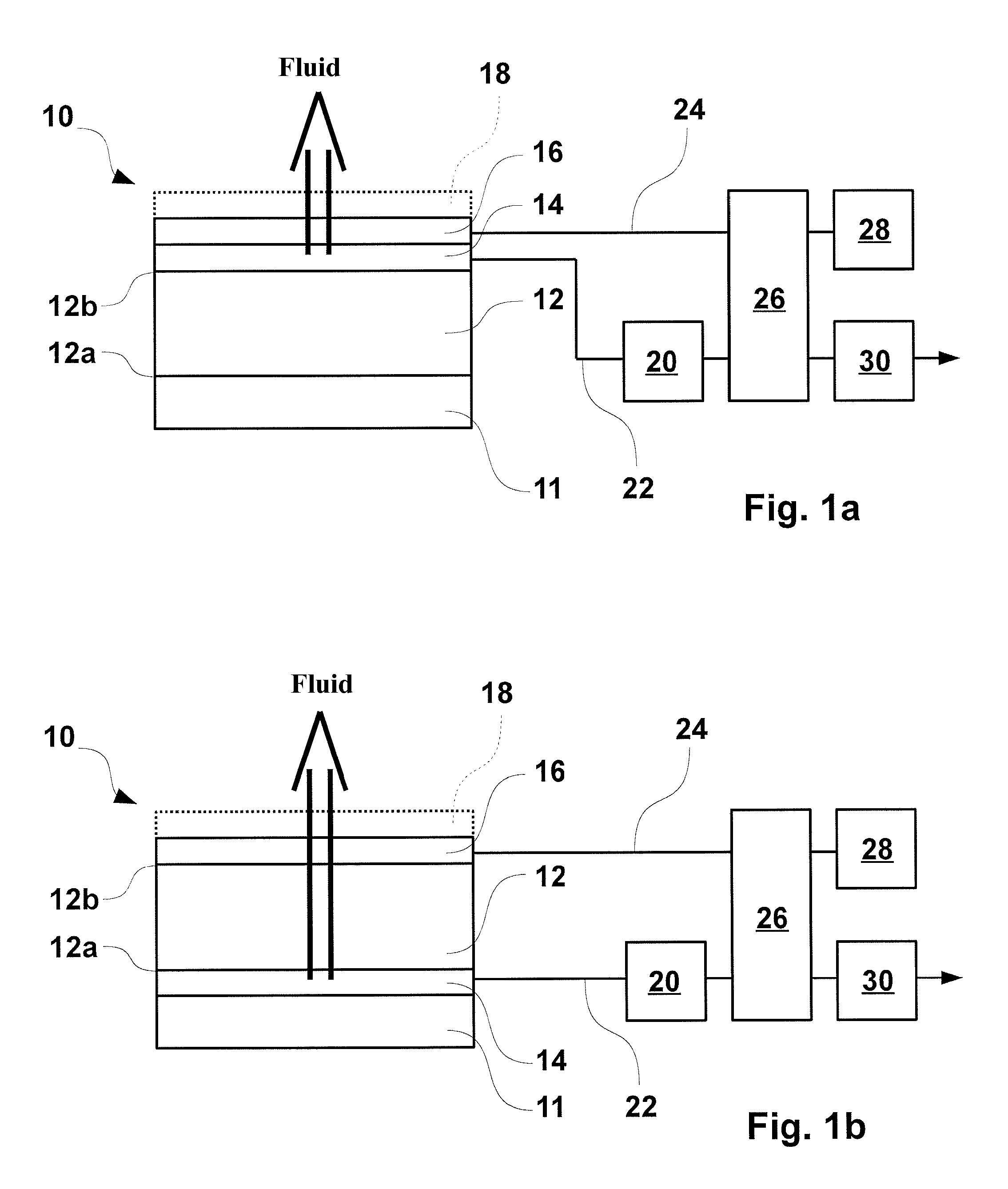
[0177]FIG. 1b illustrates a sensor 10 made by using, for example, microsystem manufacturing technologies according to the invention.

[0178]The operating elements already described in relation to the sensor illustrated in FIG. 1a remain the same and are therefore not described again.

[0179]The arrangement of the sensor of FIG. 1b is different from that of FIG. 1a to the degree in which the heating element 14 and the temperature measuring element 16 are located, not on the same side of the substrate 12, but on either side of the latter.

[0180]Actually, the temperature measuring element 16 is located facing the surface 12b of the substrate and, for example, in contact with the latter (while one or several intermediate layers can be located between these two elements), and the heating element 14 is located between the surface 12a of the substrate and the heat insulator 11.

[0181]In this arrangement, the two operating elements 14 and 16 of the sensor are spaced apart from one another at a di...


PUM

PropertyMeasurementUnit
temperatureaaaaaaaaaa
surface areaaaaaaaaaaa

Abstract

A sensor (10; 34) for measuring and/or detecting fouling that forms directly or indirectly on a so-called front surface of the sensor, includes the following in the form of a plurality of superimposed layers: —at least one heating element (14) that is able to diffuse, on command, a homogenous, monitored heat flow whose heat output is less than 200 mW, —a heat insulator (11) located on the side opposite the front surface of the sensor to prevent dissipation of the heat flow from the opposite side, —at least one temperature measuring element (16) that is placed in the homogenous heat flow diffused by the at least one heating element and that offers a precision of temperature measurement of better than 0.1° C., and —a substrate (12; 42) on which the layers of the at least one heating element and at least one temperature measuring element are connected.

Description

FIELD OF THE INVENTION[0001]The invention relates to a sensor and a system for measuring or detecting the fouling of a reactor or a pipe containing a fluid.BACKGROUND OF THE INVENTION[0002]On industrial sites, there are different types of installations in which fluids of various types circulate.[0003]These installations comprise pipes in which fluids circulate and can likewise comprise reactors such as, for example, heat exchangers.[0004]In this exact case, the fouling of such installations can have adverse effects to the degree it is capable of affecting the performances of the installations (for example, the efficiency of an industrial process).[0005]Moreover, when fouling forms on the inside wall of a pipe or a reactor, it should be promptly cleaned.[0006]However, it is necessary that this fouling be continuously detectable by the operators or the maintenance personnel of the installation in order to be able to assess, within the framework of preventive maintenance, the best time...

Claims


Application Information

Patent Timeline
Patent Type & Authority Patents(United States)
IPC IPC(8): G01N17/00G01K1/00G01N25/18
CPCG01N25/18G01N17/008
Inventor AURET, LAURENTFLOURENS, FREDERICFILLAUDEAU, LUC
Owner AQUALABO SERVICES
Why Eureka
Try Eureka