
Method and apparatus for treating a video signal

a video signal and video technology, applied in the field of video signals, can solve the problems of video signals that have originated partly from film and partly from video, image from frame to frame no longer complement each other, and still a problem, and achieve the effect of reliably indicating when and reliably detecting the cessation of the 3:2 pull-down treatmen

Inactive Publication Date: 2007-06-21
TEXAS INSTR INC
View PDF7 Cites 9 Cited by
  • Summary
  • Abstract
  • Description
  • Claims
  • Application Information

AI Technical Summary

Benefits of technology

The present invention provides a method and apparatus for detecting when a video signal has undergone 3:2 pull-down treatment and when the video signal stream changes from a film mode. This technology can reliably indicate the cessation of film mode content and can be used in various applications such as video processing and video analysis.

Problems solved by technology

However, when an object In a picture moves, the images from frame to frame no longer complement each other and there are interlacing artifacts, such as “combing” (manifested in jagged vertical edges) and “line twitter” (manifested in horizontal displacement of a portion of the image).
However, in the case of newer progressive-scan television formats there is still a problem.
However, in video signals that have originated from a film format (sometimes referred to as having film content), there is a problem if the video signal is displayed without first reversing any 3:2 pull-down treatment to which the video signal may have been subjected.
Video signals that have originated partly from film and partly from video are particularly problematic.
However, the inventor has discovered that the prior art approach described in connection with FIG. 1 is not reliable in detecting an end to a film mode—that is an end to application of a 3:2 pull-down treatment—in a video signal.
A problem is that there may be noise present in the signal being evaluated, and noise may give false values that are used in the field-to-field comparisons.
Noise can give false results using the prior art approach to detecting an end of 3:2 pull-down treated signals.

Method used


Image

  • Method and apparatus for treating a video signal
  • Method and apparatus for treating a video signal
  • Method and apparatus for treating a video signal

Examples


Embodiment Construction

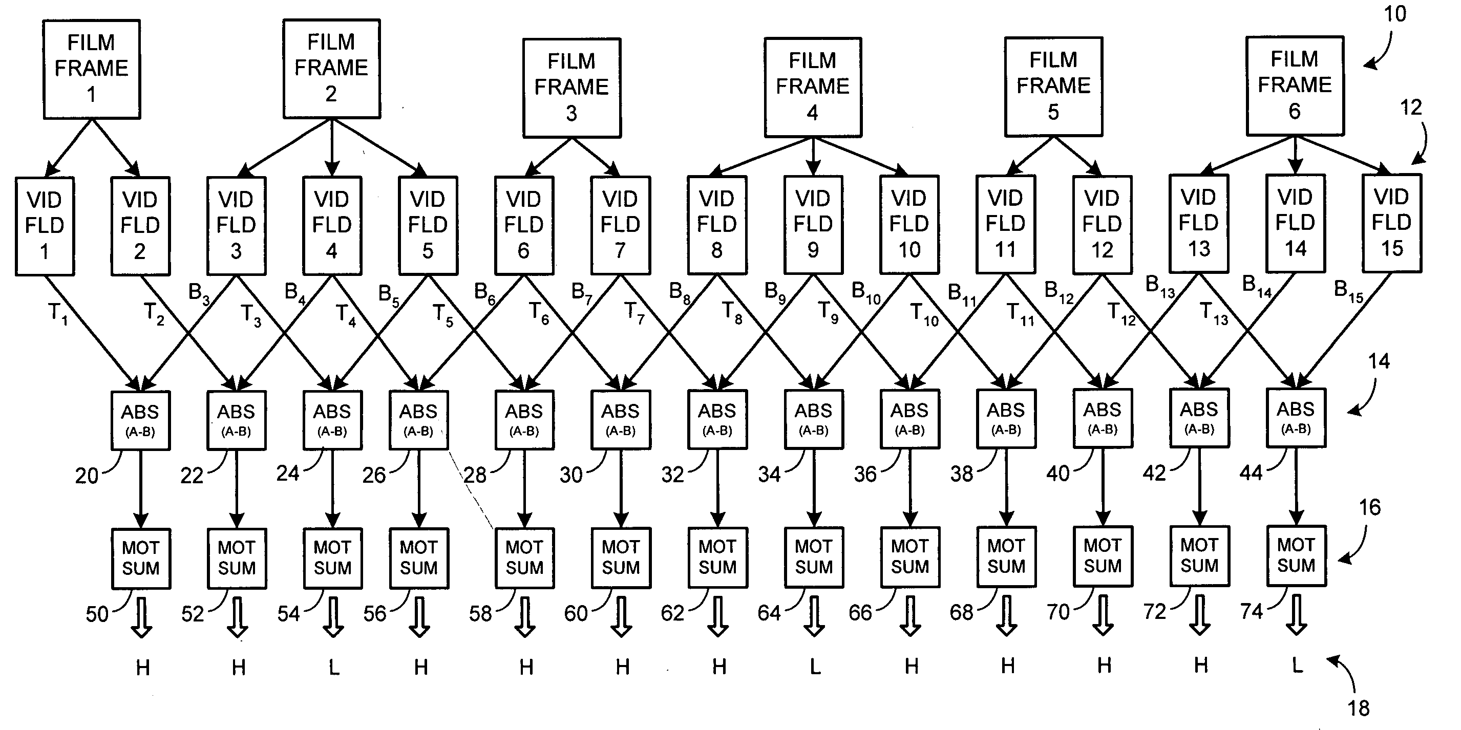
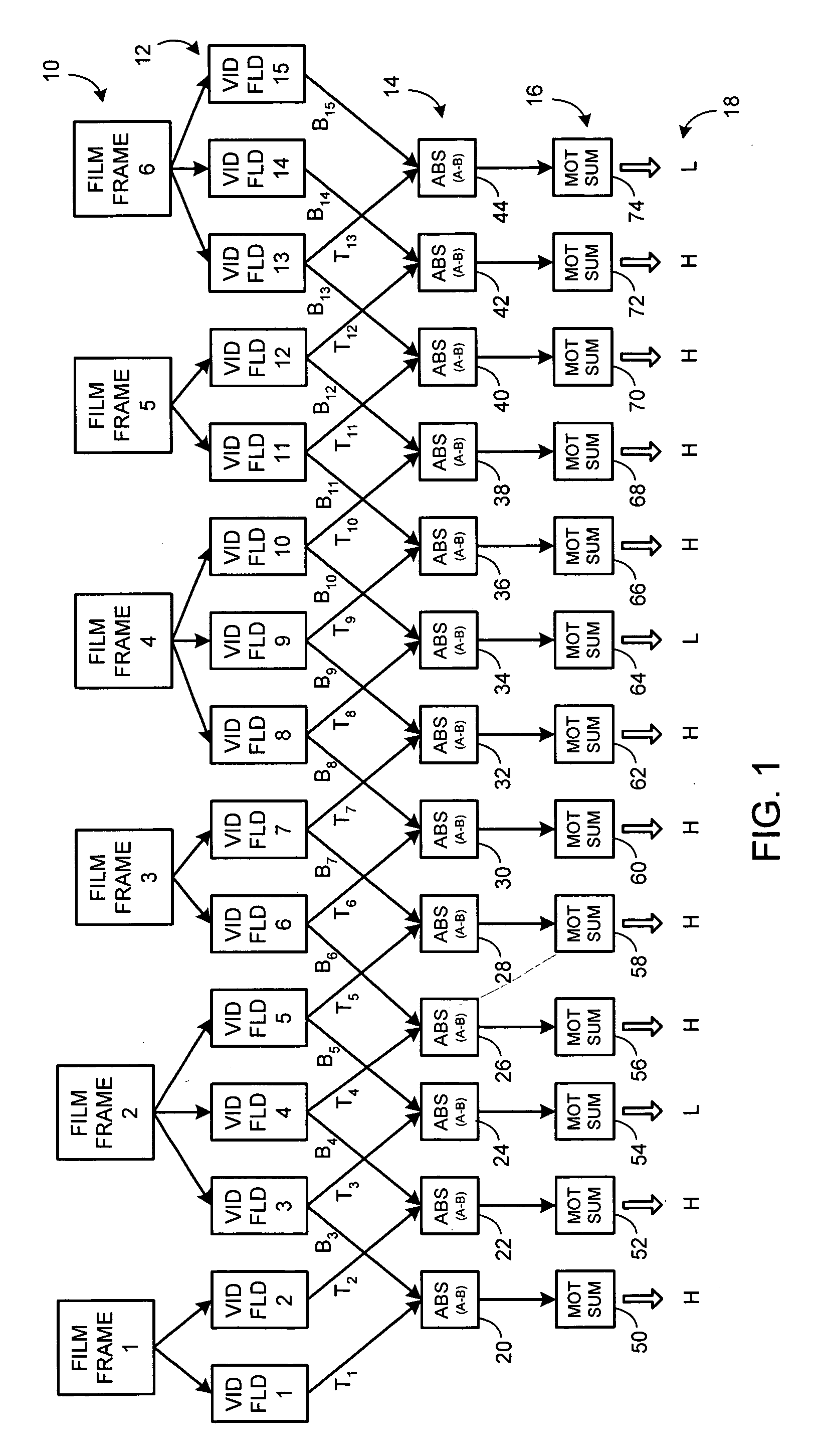
[0019]FIG. 1 is a schematic diagram illustrating the process of 3:2 pull-down conversion of motion picture film images to a video format. In FIG. 1, a first row 10 of frames contains a consecutively occurring series of film frames: Film Frame 1, Film Frame 2, Film Frame 3, Film Frame 4, Film Frame 5, Film Frame 6. Of course, more film frames may follow Film Frame 6, but in order to simplify FIG. 1, only six film frames are illustrated. Film Frames 1-6 are recorded and are presented for display at a speed of 24 frames per second.

[0020]As mentioned earlier herein, video signals may be recorded at a speed of 60 fields per second. A process known in the industry as 3:2 pull-down is employed to convert film recordings for compatible display with video equipment. Accordingly, in FIG. 1 a stream of video fields (VID FLD) is illustrated in a second row 12: VID FLD1 through VID FLD 15. Of course, more video fields may follow VID FLD 15, but in order to simplify FIG. 1, only fifteen video fie...


PUM


Abstract

A method for treating a video signal including a plurality of consecutive video fields; at least some video fields of the plurality of video fields contributing to a plurality of substantially successively occurring motion sums; includes: (a) Effecting successive comparison of selected of the motion sums with at least one motion sum threshold in a predetermined cycle. The motion sum threshold is related with at least one earlier-occurring motion sum. The predetermined cycle establishes the successive comparison for evaluating whether the selected motion sums occur in a pattern characteristic of film mode content. (b) Treating the video signal as containing film mode content so long as the successive comparison indicates film mode content. (c) Treating the video signal as not containing the film mode content when a predetermined number of the successive comparisons indicate no film mode content.

Description

[0001]This application claims benefit of prior filed copending Provisional Patent Application Ser. No. 60 / 751,157, filed Dec. 16, 2005.BACKGROUND OF THE INVENTION[0002]The present invention is directed to video signals, and especially to video signals containing a portion of their content in film mode having been subjected to a pull-down treatment, and containing a portion of their content in a video mode not having been subjected to a pull-down treatment.[0003]Interlaced NTSC (National Television Standards Committee) television is based upon an interlaced 60 frames per second. Televisions create images by scanning lines on the screen face, left-to-right and top-to-bottom to produce a picture on the entire screen. The images that make up the picture are alternating interlaced fields—one field consists of odd lines (1, 3, 5, . . . through 525) and the other field consists of even lines (2, 4, 6, . . . through 524). As a result only half of the picture is drawn every 1 / 60 second. Each...

Claims


Application Information

Patent Timeline
Patent Type & Authority Applications(United States)
IPC IPC(8): H04N7/12H04N5/253
CPCH04N7/0115
Inventor MONTGOMERY, CLAY D.
Owner TEXAS INSTR INC
Learn More