Straight-tube LED lamp switch device and straight-tube LED lamp using the same

a technology of led lamp switch device and led lamp, which is applied in the direction of contact mechanism, coupling device connection, lighting and heating apparatus, etc., can solve the problem that the state of application of led electricity cannot be properly changed to an on sta

Inactive Publication Date: 2012-06-21
ALPS ALPINE CO LTD
View PDF4 Cites 9 Cited by
  • Summary
  • Abstract
  • Description
  • Claims
  • Application Information

AI Technical Summary

Benefits of technology

[0010]Embodiments of the present disclosure provide a straight-tube LED lamp switch device that can reliably change an application state of electricity to a LED to an ON state even if positions of electrodes in a socket vary. The embodiments of the present disclosure also provide a straight-tube LED lamp using the straight-tube LED lamp switch device.

Problems solved by technology

However, the positions of the electrodes exposed from the holes provided at the socket of the fluorescent-lamp fixture, i.e., distances from the surface of the socket with the holes to the electrodes may vary depending on a manufacturer, an error (tolerance) in dimension of a part, and the like.
The application state of electricity to the LED may not be properly changed to an ON state.

Method used


Image

  • Straight-tube LED lamp switch device and straight-tube LED lamp using the same
  • Straight-tube LED lamp switch device and straight-tube LED lamp using the same
  • Straight-tube LED lamp switch device and straight-tube LED lamp using the same

Examples


second embodiment

[0131]A switch device 200 according to an exemplary embodiment differs from the switch device 1 for example, in configurations of second terminals 240, a driving member 250, and a movable contact unit 260. The configuration of the switch device 200 is described mainly for points different from the first embodiment. In the switch device 200, like reference signs refer like components having functions common to those of the switch device 1 according to the first embodiment, and the description thereof is omitted.

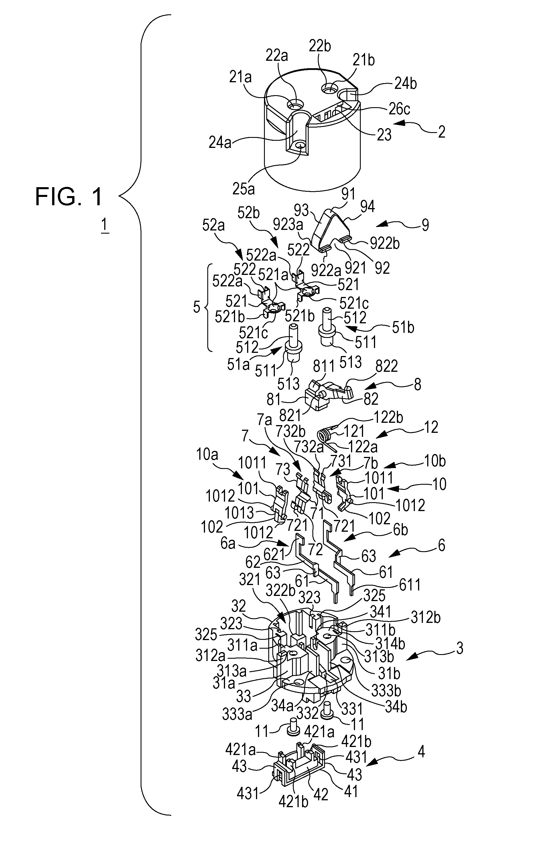
[0132]FIG. 16 is an exploded perspective view showing a general configuration of the switch device 200. In the following description, the upper left side in FIG. 16 is referred to as the “rear side of switch device 200” or merely “rear side,” and the lower right side in FIG. 16 is referred to as the “front side of switch device 200” or merely “front side.”

[0133]As shown in FIG. 16, the switch device 200 may include an outer case 210 that may form a housing of a device body and...


PUM


Abstract

A straight-tube LED lamp switch device includes a first terminal protruding from a housing; an operating body having an operating portion that can receive a pressing operation into the housing; a second terminal that is brought into conduction with the first terminal by the pressing operation on the operating body; and a torsion spring that restores the operating body to an initial state before the pressing operation. A position of a distal end portion of the operating body in the initial state protrudes outside with respect to a distal end portion of the first terminal.

Description

CLAIM OF PRIORITY[0001]This application contains information related to and claims benefit of the following Japanese Patent Applications: No. 2010-283546 filed on Dec. 20, 2010, No. 2010-283547 filed on Dec. 20, 2010, and No. 2011-206306 filed on Sep. 21, 2011. The contents of each of the aforementioned applications are hereby incorporated by reference in their entirety.BACKGROUND OF THE DISCLOSURE[0002]1. Field of the Disclosure[0003]Embodiments of the present disclosure relate to a straight-tube light-emitting diode (LED) lamp switch device that is used for a straight-tube LED lamp and is attached to a socket of a lamp fixture, and also relates to a straight-tube LED lamp using the switch device.[0004]2. Description of the Related Art[0005]In recent years, a LED lamp using a LED as a light source is being popular. The LED lamp can markedly reduce power consumption and carbon dioxide emission and markedly increase the life of a product as compared with a conventional lamp. A straig...

Claims


Application Information

Patent Timeline
Patent Type & Authority Applications(United States)
IPC IPC(8): F21S4/00H01H3/02
CPCF21V23/06F21Y2101/02H01H23/168F21K9/175H01R33/06H01R33/96F21V25/04H01R13/7032F21Y2115/10F21K9/272F21V17/00F21V19/00H01H13/26
Inventor MORI, TOSHIHARUKAWASE, TATSUAKIHAYASHI, MAKOTOTANAKA, TAKUYAFUJIWARA, SYUJI
Owner ALPS ALPINE CO LTD
Why Eureka
Try Eureka