Method and system for detecting when an end of train has passed a point

a technology of detecting and passing a point, applied in the field of railways, can solve the problems of difficult or impossible visual determination of the end of a train passing a point, collision between two trains, and modern trains can be hundreds of yards long,

Inactive Publication Date: 2005-07-05
SIEMENS MOBILITY INC
View PDF56 Cites 97 Cited by
  • Summary
  • Abstract
  • Description
  • Claims
  • Application Information

AI Technical Summary

Benefits of technology

[0012]The present invention determines that an end of train has passed a point through the use of positioning systems located at the head of the train and the end of the train. In a first method, a control unit will obtain the train's position at a point of interest (e.g., a switch or block boundary) from the HOT positioning system. The control unit will then determine when the train has traveled a distance equal to the length of the train. This can be done either by integrating successive reports from the positioning system (that is, determining a difference in position between successive reports and adding the differences to determine a total distance), or by periodically determining a distance between the position of the point of interest and the position reported by the positioning system until such time as the distance is greater than the length of the train. When the distance traveled by the head of the train equals or exceeds the length of the train, the control unit will interrogate the positioning system at the end of the train. If the difference between this position and the position reported by the head-of-train positioning system at the point of interest exceeds a threshold

Problems solved by technology

If such a warrant to occupy the first block is issued to the second train before the end of the first train has cleared that block, a collision between the two trains may result.
Modern trains can be hundreds of yards long, and an engineer in the lead locomotive often cannot see the end of the train.
Operating trains at night or during bad weather may also make visually determining that the end of a train has passed a point difficult or impossible.
Thus, visual methods are not sufficient.
However, with this method, it is important to take into account the possibility that one or more end cars of a train may become uncoupled from the remainder of the train.
However, with these devices the motion sensors sometimes break or give false readings and

Method used


Image

  • Method and system for detecting when an end of train has passed a point
  • Method and system for detecting when an end of train has passed a point
  • Method and system for detecting when an end of train has passed a point

Examples


second embodiment

[0029]FIG. 3 is a flowchart of the operation of the control module 110 according to the invention. The method illustrated in FIG. 3 is similar to the method illustrated in FIG. 2, but differs in the way in which the control module 110 determines that the head-of-train has traveled a distance equal to the length of the train. The step in the method of FIG. 2 can be peformed by successively querying the GPS system to determine the distance between the point of interest and the current head-of-train location. The distance may be determined by simply calculating a linear distance, but doing so can be disadvantageous in that, for curved sections of track, the linear distance will be shorter than the true “track distance” (i.e., the distance that the train has traveled over the track), which will result in an unnecessary delay in determining that the HOT has traveled a distance equal to the length of the train. This step may also be performed using track information stored in the map data...

third embodiment

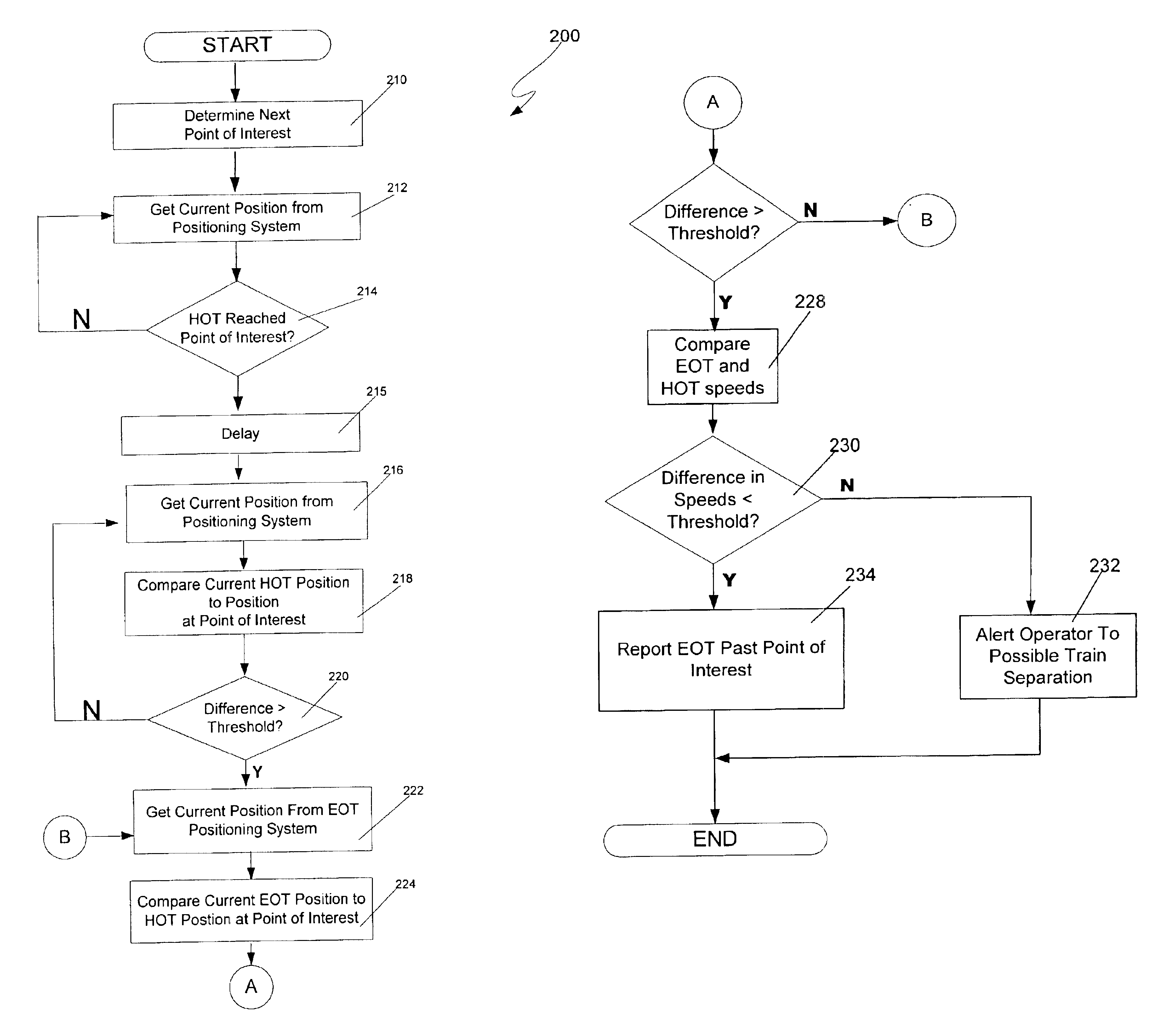
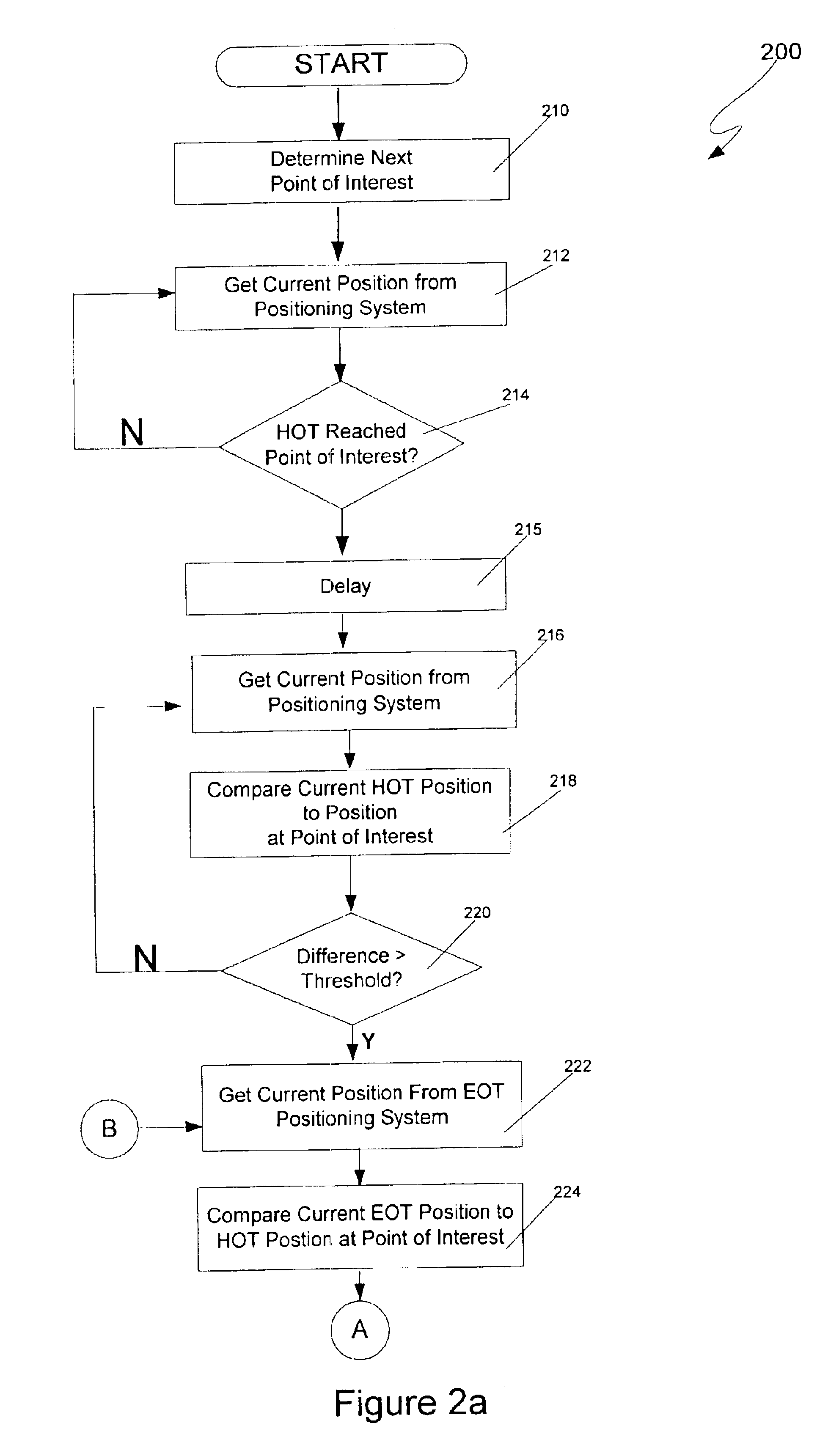
[0031]FIG. 4 is a flowchart 400 illustrating the operation of the control module 110 according to the invention. The control module 110 determines the location of the next point of interest at step 402. As discussed above, the next point of interest may be determined in any number of ways including, for example, using information from the map database 140, or it may be obtained from a dispatcher (e.g., in a warrant / authority). The control module 110 then obtains the train's current position from information provided by the HOT positioning system 120 at step 404. If the current train position as reported by the HOT positioning system 120 indicates that the HOT has not yet reached the point of interest at step 406, step 404 is repeated.

[0032]When the HOT has reached the point of interest at step 406, the control module 110 then obtains the current EOT position from the EOT positioning system 130 and temporarily stores it at step 408. The control module 110 then delays a short period (...


PUM


Abstract

A controller determines that an end of train (EOT) has passed a point through the use of positioning systems at the head of the train (HOT) and the EOT. In a first method, the controller obtains the HOT position at a point of interest from the HOT positioning system. The controller then determines when the train has traveled a distance equal to the length of the train and then interrogates the EOT positioning system. If the difference between this position and the position reported by the HOT positioning system at the point of interest exceeds a threshold, then the EOT has passed the point. In a second method, when the HOT positioning system reaches a point of interest, the position reported by the EOT positioning system is integrated until the total distance traveled by the EOT equals the length of the train.

Description

BACKGROUND OF THE INVENTION[0001]1. Field of the Invention[0002]The invention relates to railroads generally, and more particularly to a method and system for detecting when an end of train passes a point such as a mile marker, switch, siding or other location of interest.[0003]2. Discussion of the Background[0004]It is often important to be able to determine that a railroad has passed a particular point in a railroad. For example, in a train control method known as Track Warrant Control (TWC), a railroad is divided into sections referred to as blocks and a dispatcher gives each train warrants, or authorities, to occupy and / or move in one or more blocks. The blocks are usually (but not necessarily) fixed, with block boundaries usually (but not necessarily) being identified with physical locations on the railroad such as mileposts, sidings, and switches. In this system, a train in a first block (or group of blocks) receives a warrant to occupy a second adjacent block (or group of blo...

Claims


Application Information

Patent Timeline
IPC IPC(8): G06F17/00G08G1/123B61LB61L15/00B61L25/02
CPCB61L15/0054B61L25/021B61L25/025B61L25/026B61L2205/04B61L15/0072
Inventor KANE, MARK EDWARDSHOCKLEY, JAMES FRANCISHICKENLOOPER, HARRISON THOMAS
Owner SIEMENS MOBILITY INC
Why Eureka
Try Eureka