Underbody mounting system

Inactive Publication Date: 2005-07-12
PEERLESS INDS
View PDF42 Cites 44 Cited by
  • Summary
  • Abstract
  • Description
  • Claims
  • Application Information

AI Technical Summary

Benefits of technology

[0006]A mounting system in accordance with the principles of the present invention provides a simple device for mounting a display unit on the underside of a body such as a cabinet or shelf, while also providing the user with the ability to fully retract the display unit

Problems solved by technology

This is primarily due to the fact that a person's counter and desk space can be quite limited, therefore necessitating placement of devices such as LCD units positioned above the desk.
For example, if an LCD unit is mounted on the underside of a shelf or cabinet but remains positioned such that it is viewable 24 hours a day, then the user loses a significant amount of space that could be used for other purposes when the user is not viewing the LCD unit.
A number of underbody mounting systems

Method used


Image

  • Underbody mounting system
  • Underbody mounting system
  • Underbody mounting system

Examples


Embodiment Construction

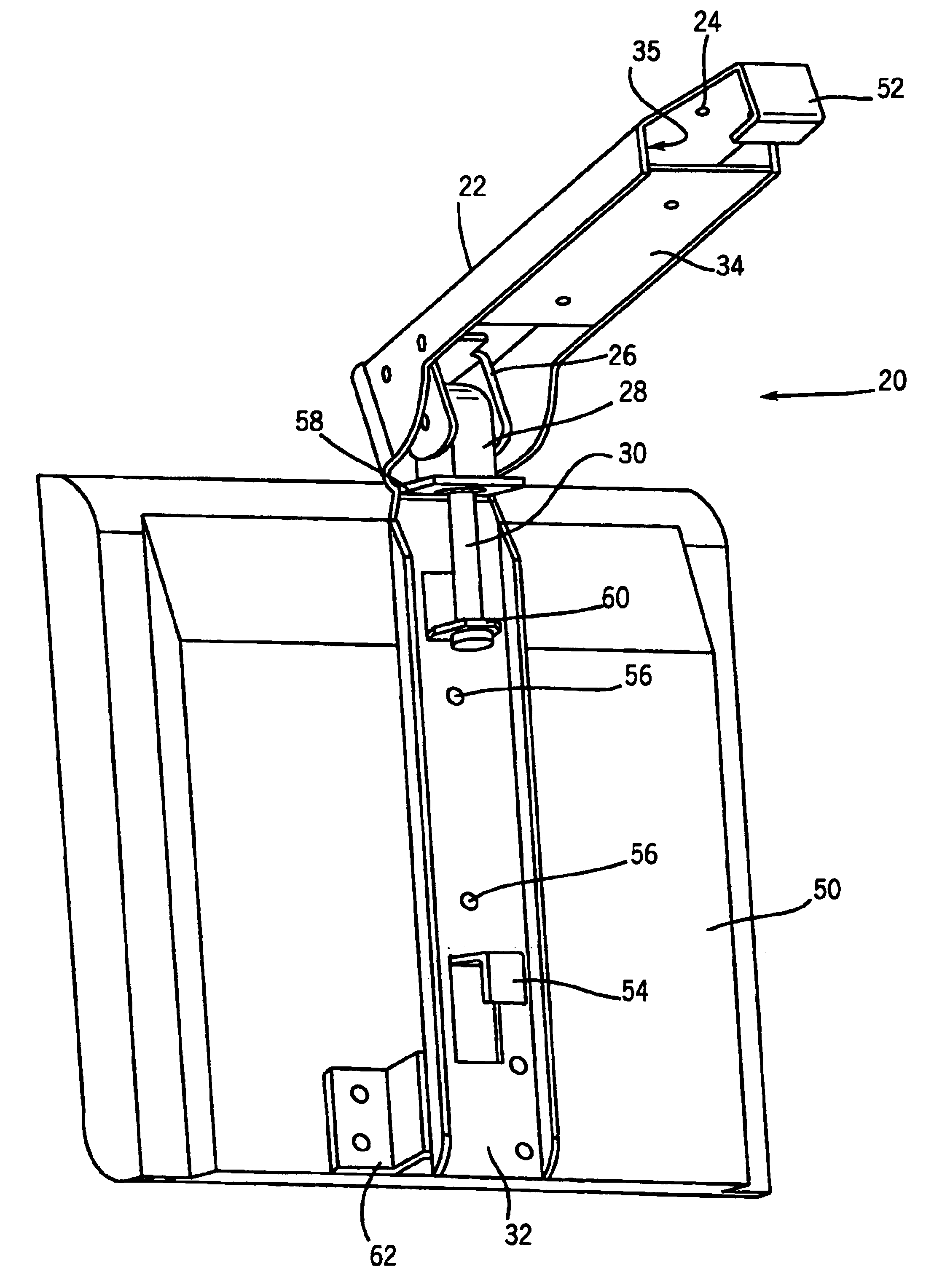
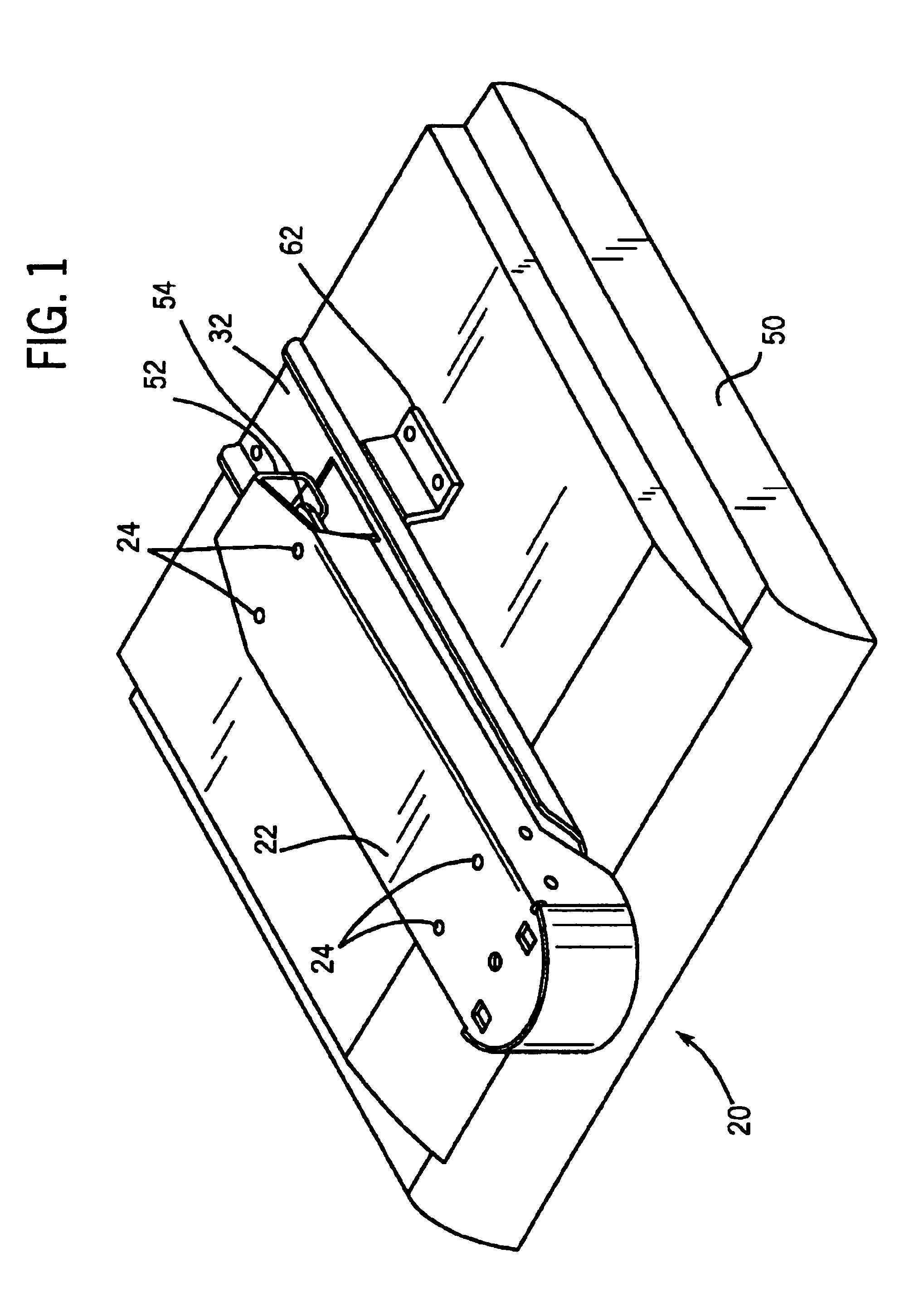
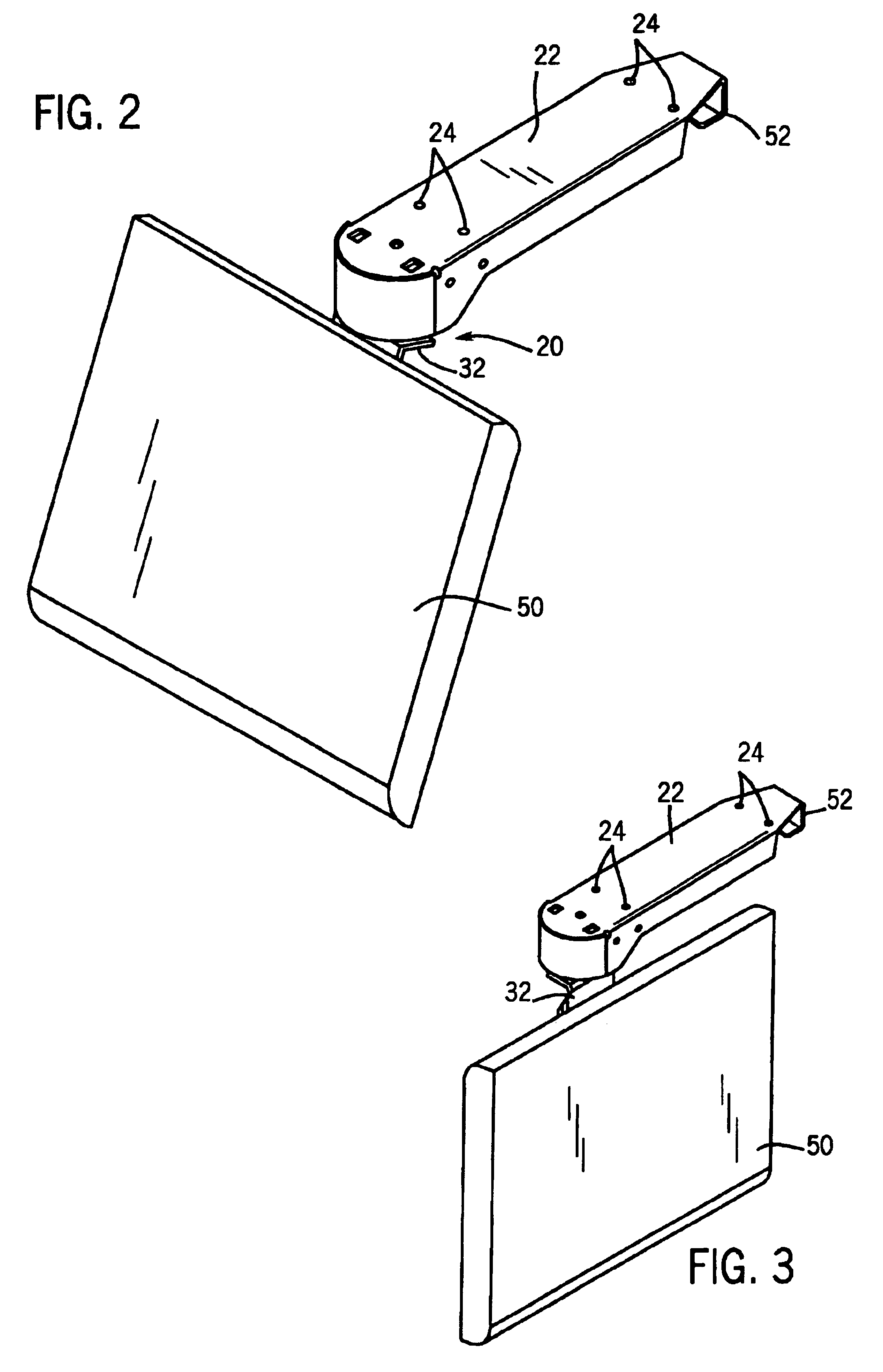
[0016]An underbody mounting system, according to one embodiment in accordance with the principles of the present invention, is shown generally at 20 in FIGS. 1-5. The underbody mounting system 20 comprises a mounting bracket 22 and a display system bracket 32. The mounting bracket 22 is coupled to a pivot bracket 26 which is operatively connected to a tilt block 28. The tilt block 28 is operatively connected to the display system bracket 32 by a carriage bolt 30. As shown in FIG. 4, the mounting bracket 22 includes a cover piece 34, which define a space 35 between the mounting bracket 22 and the cover piece 34. The space 35 may be used to route electrical cords, speaker cords, and / or other types of cords away from the display. This provides the user with the additional benefit of “hiding” the cords from view, providing a more efficient use of space and removing a potential obstruction or hazard from adjacent the display unit.

[0017]The mounting bracket 22 includes a plurality of moun...


PUM


Abstract

A mounting device for a display device comprising a mounting bracket coupled to the underside of a body and a pivot bracket coupled to the mounting bracket. A pivot bracket is coupled to the mounting bracket at one end thereof. A tilt block is coupled to the pivot bracket and is rotatable about an axis substantially parallel to the body. A carriage bolt is coupled to the tilt block and is rotatable about an axis substantially perpendicular to the body. A display system bracket is operatively connected to the carriage bolt. An interface bracket is connected to the display system bracket and is capable of engaging a display device.

Description

FIELD OF THE INVENTION[0001]The present invention is directed to a system for mounting a display unit to the underside of a body such as cabinets, shelves or similar structures.BACKGROUND OF THE INVENTION[0002]Mounting systems for televisions monitors and liquid crystal display (LCD) units have been used for a number of years. Mounting systems are conventionally used to position a television or LCD display unit at a particular height and position that is desired by a particular user.[0003]In recent years, both the size and the price of LCD units have decreased dramatically. This decrease in price has resulted in a surge in popularity and sales of LCD units. With this increase in popularity, however, there has also been an increase in the number of ways in which people would like to use LCD units. For example, it has become increasingly desirable to have an LCD unit mounted on the underside of a cabinet or shelf, as opposed to resting directly or indirectly upon a desktop or tabletop...

Claims


Application Information

Patent Timeline
IPC IPC(8): F16M11/12F16M11/02
CPCF16M11/08F16M11/12F16M11/2021F16M13/027Y10S248/918Y10S248/921Y10S248/922Y10S248/92Y10S248/923
Inventor GILLESPIE, JOHN
Owner PEERLESS INDS
Why Eureka
Try Eureka