Brake pedal assembly with variable ratio

Inactive Publication Date: 2005-07-19
KSR IP HLDG
View PDF31 Cites 16 Cited by
  • Summary
  • Abstract
  • Description
  • Claims
  • Application Information

AI Technical Summary

Benefits of technology

[0010]One advantage of the present invention is that a variable ratio brake pedal assembly is provided that improves brake effectiveness. Another advantage of the present invention is that a variable ratio brake pedal assembly is provided that varies the pedal ratio during the pedal stroke to improve brake feel throughout the pedal stroke. A further advantage of the present invention is that the master cylinder and bra

Problems solved by technology

A high pedal ratio can be effective, but the long pedal travel results in a “spongy” feel to the brakes.
Conversely, a low pedal ratio is the result of a shorter pedal travel, however, the shorter pedal travel results in an abrupt or sharp braking action.
While this system works, the large angular displacement at the second

Method used


Image

  • Brake pedal assembly with variable ratio
  • Brake pedal assembly with variable ratio
  • Brake pedal assembly with variable ratio

Examples


Example

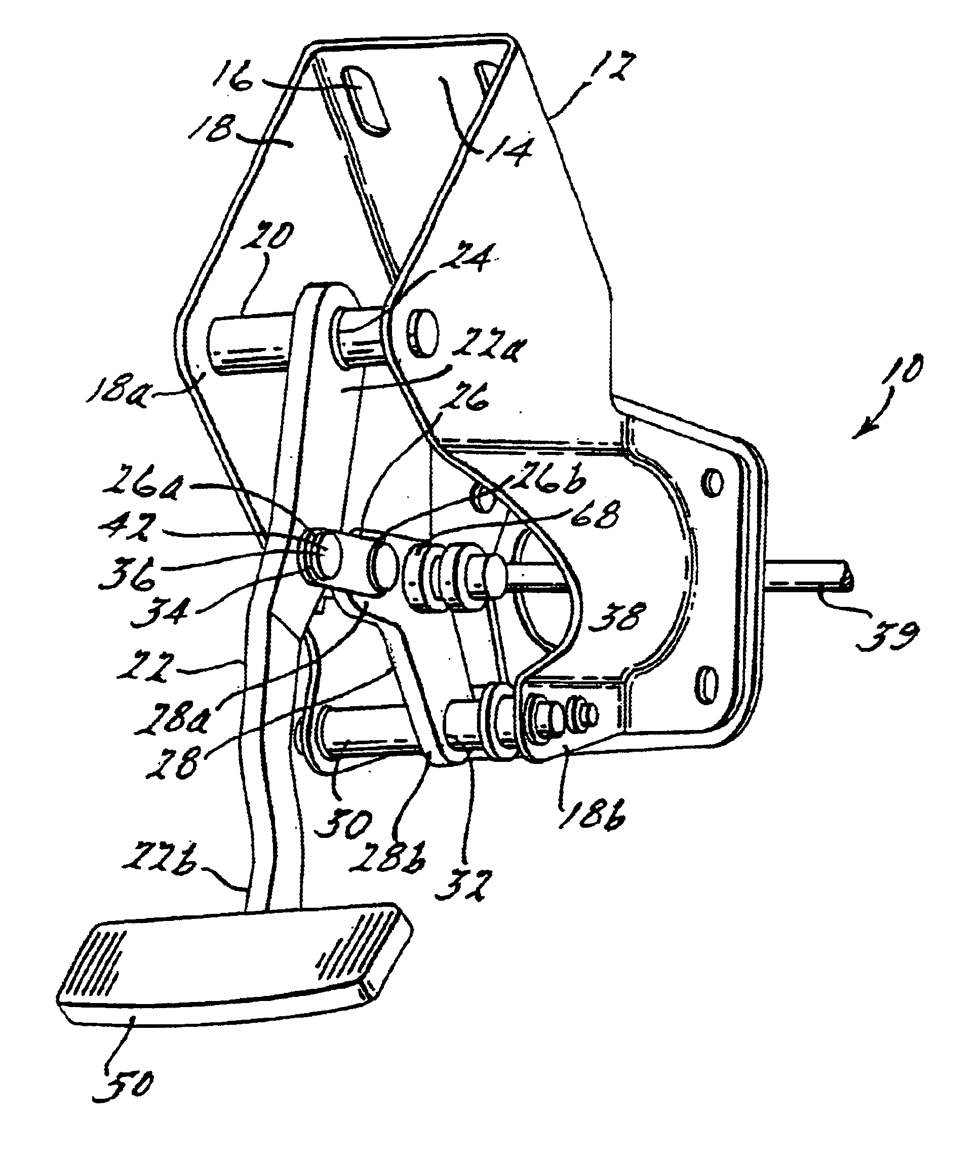
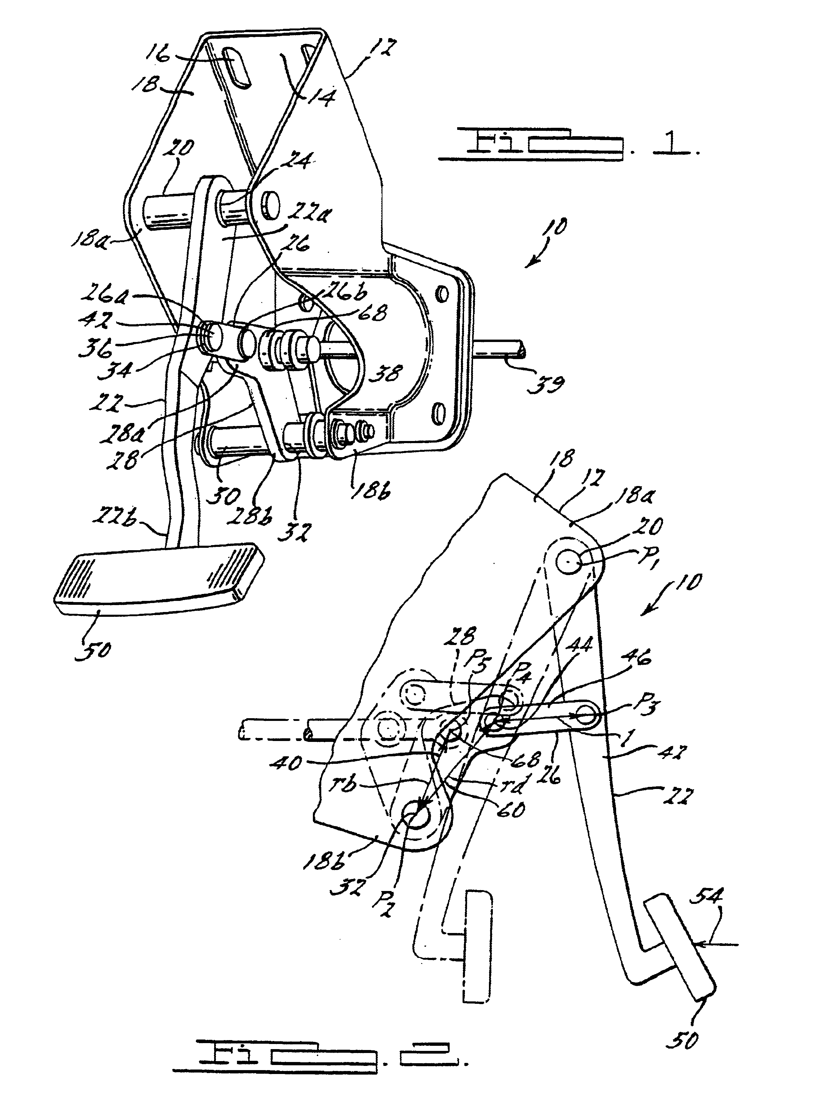
[0018]Referring to FIGS. 1-6, a variable ratio brake pedal assembly 10 for translating a signal between a vehicle operator or driver (not shown) and a brake actuating mechanism (not shown) is illustrated. As is known in the art, the brake pedal assembly is part of the brake system for slowing down the vehicle. In a fixed brake pedal assembly, the height of the pedal pad (to be described) with respect to the floor is a predetermined height. In an adjustable brake pedal assembly, the initial position of the pedal pad relative to a portion of the vehicle, such as the floor, is adjustable by the driver. It should be appreciated that in this example, the brake pedal assembly 10 is a fixed height brake pedal assembly, although an adjustable height brake pedal assembly is contemplated. An example of an adjustable height brake pedal assembly is disclosed in commonly assigned U.S. patent application Ser. No. 09 / 882,981, which is incorporated herein by reference.

[0019]The variable ratio brake...


PUM


Abstract

A variable ratio brake pedal assembly includes a support bracket having a mounting face and two spaced apart side arms extending from opposing edges of the mounting face. The brake pedal assembly also includes a pedal arm pivotally mounted to the support bracket at a first pivot point, and having a pedal pad mounted to a lower end of the pedal arm. The brake pedal assembly also includes a pedal link having a first end and a second end, such that the first end is pivotally connected to the pedal arm at a third pivot point, and a brake booster link having a first end and a second end, and the first end of the brake booster link is pivotally mounted to the second end of the pedal link at a fourth pivot point and the second end of said brake booster link is pivotally mounted to the support bracket at a second pivot point. The brake pedal assembly further includes a brake booster rod attaching means located on the brake booster link at a fifth pivot point, such that the fifth pivot point is located on the brake booster link so that a distance between the second pivot point and the fifth pivot point is less than a distance between the second pivot point and the fourth pivot point.

Description

[0001]This application claims the benefit of Provisional Application No. 60 / 260,716, filed Jan. 10, 2001.BACKGROUND OF THE INVENTION[0002]The present invention relates generally to brake pedals, and more specifically, to a brake pedal assembly with a variable ratio linkage.[0003]Vehicles, and in particular automotive vehicles, include a brake system for controlling the movement of the vehicle. Conventional brake systems include a brake pedal for transmitting a braking force from the vehicle operator to the wheels of the vehicle. The brake pedal is operatively coupled to a brake booster via a push rod. The brake booster is operatively connected to a master cylinder, and the master cylinder is operatively connected to a braking mechanism via brake lines. The braking mechanism is coupled to a wheel of the vehicle and applies the force to the wheel to slow down the rotational movement of the wheel.[0004]Various factors influence the overall efficiency of the brake system. Examples of so...

Claims


Application Information

Patent Timeline
IPC IPC(8): B60T11/18B60T7/06B60T11/16B60T7/04G05G1/44G05G1/30G05G1/405
CPCB60T7/06B60T11/18G05G1/46G05G1/405Y10T74/20888Y10T74/20528
Inventor WILLEMSEN, LARRY G.
Owner KSR IP HLDG
Why Eureka
Try Eureka