Fixing structure

Inactive Publication Date: 2005-07-19
FUJITSU GENERAL LTD
View PDF7 Cites 3 Cited by
  • Summary
  • Abstract
  • Description
  • Claims
  • Application Information

AI Technical Summary

Benefits of technology

[0020]The present invention has been achieved to solve the above-mentioned problems, and it is an object of the invention to provide a fitting structure capable of fixing a case main body and a lid securely without looseness in the fitting portions in which the fitting portions for the case main body and the lid can be regulated in position in both the inserting and drawing directions.

Problems solved by technology

Thus, if the size of associated portions is managed strictly to remove looseness, there is a fear that the cost for the case main body 60 and the lid 70 increases.
Accordingly, the total size of the case main body is increased by the volume of the position regulating portion 84 to obtain a desired internal volume, making it difficult to miniaturize the case main body.
Thus, if the size of associated portions is managed strictly to remove looseness, there is a fear that the cost for the case main body 80 and the lid 90 increases.

Method used


Image

  • Fixing structure
  • Fixing structure
  • Fixing structure

Examples


first embodiment

[0028]Referring to FIGS. 1A to 2E, the present invention will be described below.

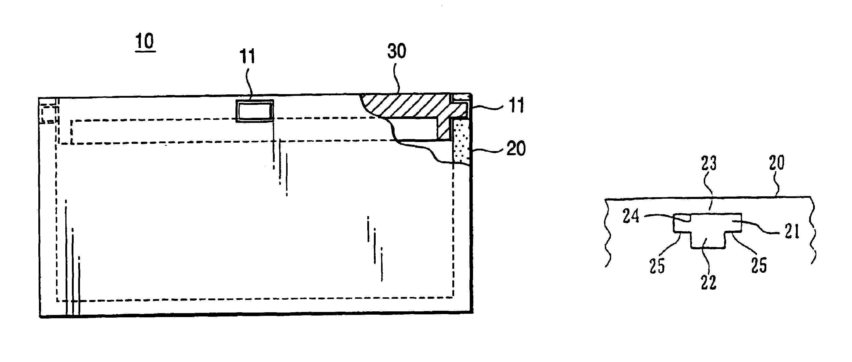
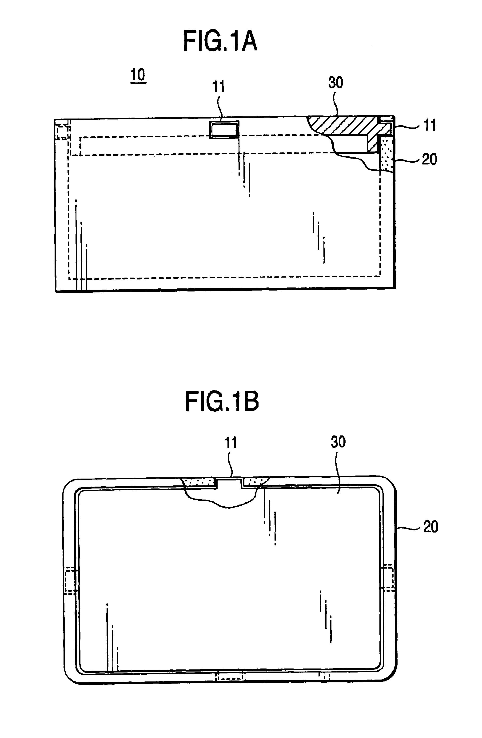
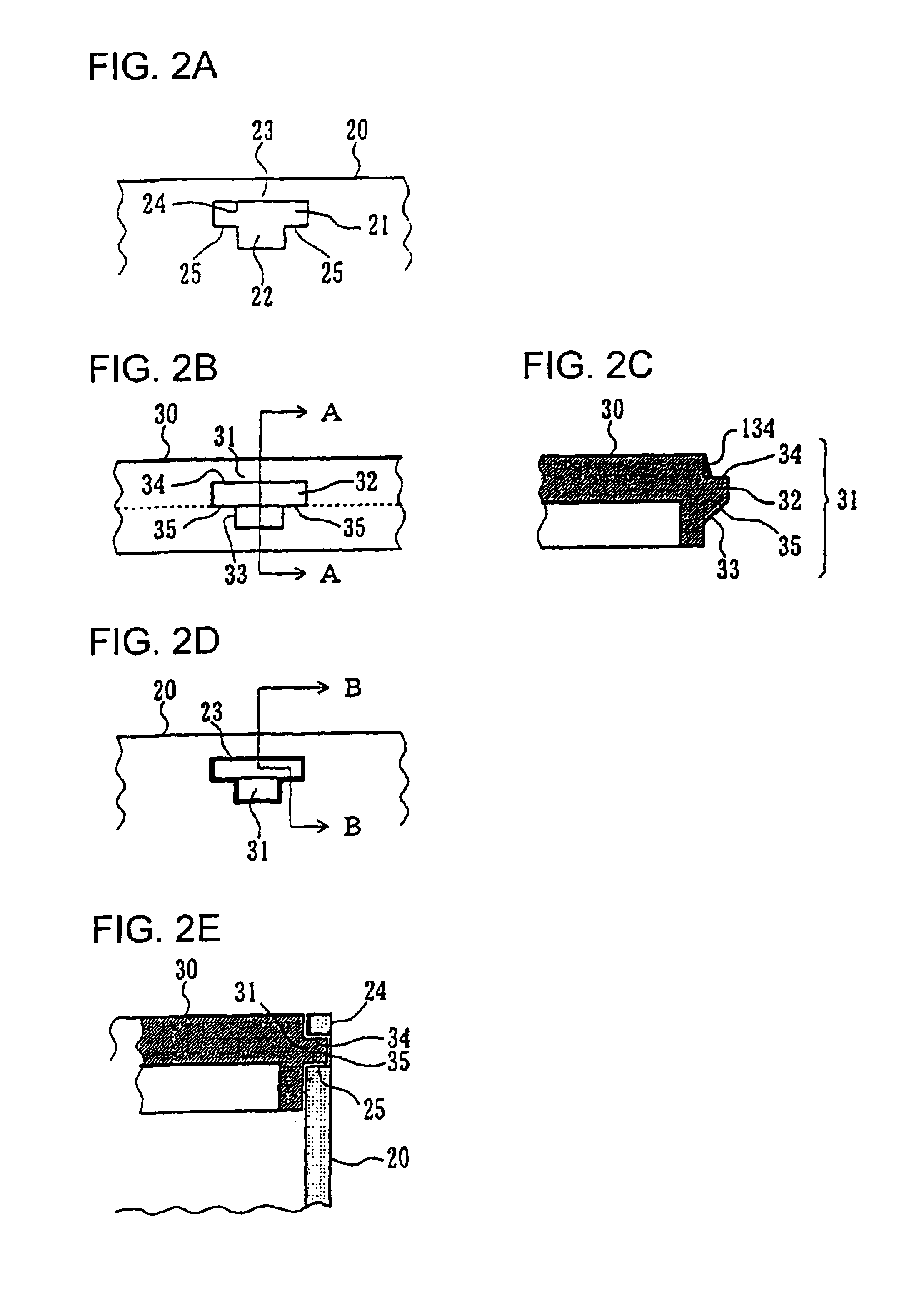
[0029]FIGS. 1A and 1B are a schematic views showing a fitting structure for a case main body and a lid according to an embodiment of the invention. FIG. 1A is a front view (partially in cross section) and FIG. 1B is a plan view (partially in cross section). FIGS. 2A to 2E are views showing fitting portions 11 of the case main body and the lid according to a first embodiment of the invention. FIG. 2A is a front view of a fitting portion in the case main body, FIG. 2B is a front view of a fitting portion in the lid, FIG. 2C is a cross-sectional view taken along the line A—A, FIG. 2D is a front view of the case main body and the lid in a fitted state, and FIG. 2E is a cross-sectional view taken along the line B—B.

[0030]Reference numeral 10 denotes a storage container for storing the essential parts of an electronic apparatus. The storage container comprises a case main body 20 and a lid 30.

[0031]The case m...

second embodiment

[0037]Referring to FIGS. 3A to 3F, the invention will be described below.

[0038]FIGS. 3A to 3F are views showing fitting portions for a case main body and a lid according to a second embodiment of the invention. FIG. 3A is a front view of a fitting portion in the case main body, FIG. 3B is a cross-sectional view taken along the line C—C, FIG. 3C is a front view of a fitting portion in the lid, FIG. 3D is a cross-sectional view taken along the line D—D, FIG. 3E is a front view of the case main body and the lid in a fitted state, and FIG. 3F is a cross-sectional view taken along the line E—E. A storage container of the second embodiment is almost the same as in the first embodiment shown in FIGS. 1A and 1B, except that the fitting portion is partially varied from the first embodiment.

[0039]The case main body 40 is a box-type case with rectangular bottom, and formed with an engagement bore 41 extending in the same direction as en end face of the opening portion in the almost central par...


PUM


Abstract

A fixing structure for fixing a case main body with a lid includes fitting portions provided for the case main body and the lid respectively. One of the fitting portions includes a fitting bore having an engagement bore to be engaged by the other of the fitting portions and a bore extending from a fitting direction terminal part of the engagement bore in a fitting direction. The other of the fitting portions includes a fitting projection portion having an engaging projection portion provided at a position corresponding to the engagement bore and a guide projection portion provided at a position corresponding to the bore. The guide projection portion has a fitting guide portion, the height of which decreases from engaging projection portion side thereof toward an end part of the guide projection portion.

Description

[0001]The present disclosure relates to the subject matter contained in Japanese Patent Application No. 2002-080279 filed Mar. 22, 2002, which is incorporated herein by reference in its entirety.BACKGROUND OF THE INVENTION[0002]1. Field of the Invention[0003]The present invention relates to a fixing structure between a supporter and a supported member, and more particularly to a fitting structure between a case main body and a lid, for instance.[0004]2. Description of the Related Art[0005]Two examples of fitting structures between a case main body and a lid for a conventional storage container, which can store essential parts of an electronic apparatus or the like, will be described below with reference to FIGS. 4A to 5E. Other parts than fitting portions in the conventional storage container as shown in FIGS. 4A to 5E are roughly the same as those shown in FIGS. 1A and 1B which will be used for explaining an embodiment of the invention.[0006]Referring firstly to FIGS. 4A to 4E, a f...

Claims


Application Information

Patent Timeline
IPC IPC(8): H02G3/08H05K5/02H05K5/03
CPCH02G3/081
Inventor WATANABE, TAKUYA
Owner FUJITSU GENERAL LTD
Why Eureka
Try Eureka