Implant for closing an opening in the annulus fibrosus

Inactive Publication Date: 2006-08-31
AESCULAP AG
View PDF9 Cites 53 Cited by
  • Summary
  • Abstract
  • Description
  • Claims
  • Application Information

AI Technical Summary

Benefits of technology

[0024] It is advantageous for the implant to be part of a set of plugs having a different height and/or width, so that during the surgical operation

Problems solved by technology

However, a problem arises from the annulus no longer being intact.
This closure is therefore

Method used


Image

  • Implant for closing an opening in the annulus fibrosus
  • Implant for closing an opening in the annulus fibrosus
  • Implant for closing an opening in the annulus fibrosus

Examples


Example

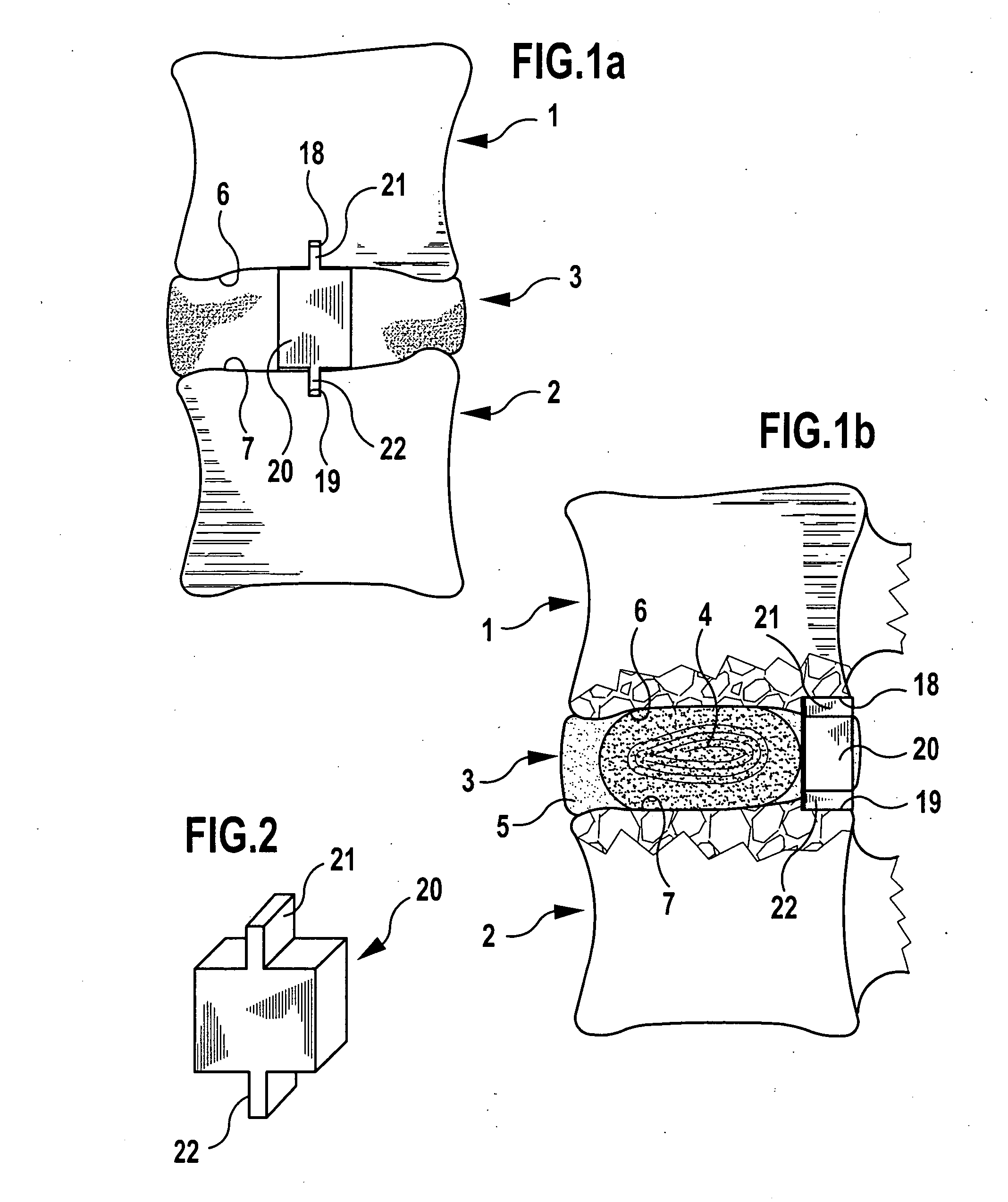
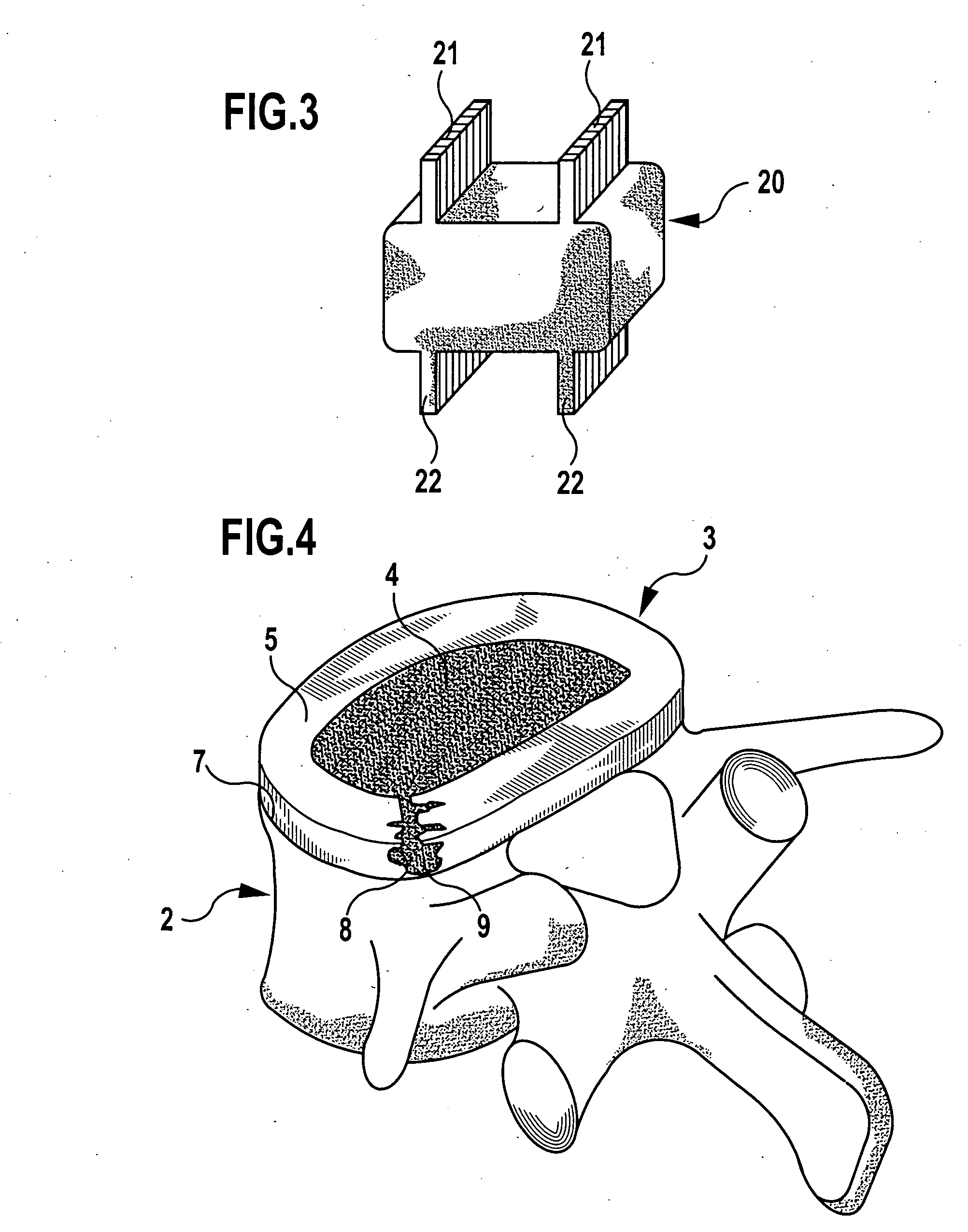
[0037] As will be apparent from the drawings, in particular, from FIGS. 1a, 1b and 4, an intervertebral disc 3 is arranged between two vertebrae 1, 2. The intervertebral disc 3 consists of the central nucleus 4 and the annulus fibrosus 5 surrounding it. The upper vertebra 1 is omitted in FIG. 4 for the sake of clarity. It shall, however, be understood that this upper vertebra 1 rests with its lower end plate 6 in a surface-to-surface manner in the same way as the lower vertebra 2 with its upper end plate 7 against the intervertebral disc 3. FIG. 4 shows schematically how through an opening 8 in the annulus fibrosus, for example, in the form of a tear, nucleus material 9 leaks out from the nucleus 4. This leaking material can bear on adjacent nerve roots and cause pain.

[0038] To repair this injury, the nucleus material 9 leaking from the opening 8 is removed in a surgical operation. This may be carried out with, for example, a forceps-like instrument 10 with which the jelly-like nuc...


PUM

PropertyMeasurementUnit
Pore sizeaaaaaaaaaa
Pore sizeaaaaaaaaaa
Adhesion strengthaaaaaaaaaa

Abstract

In an implant in the form of a plug for closing an opening in the annulus fibrosus, in order to ensure as reliable a fixing of the plug as possible and a secure closure, it is proposed that the plug have rigid anchoring elements for the end plates of adjacent vertebrae on its upper face and on its lower face, and a deformable structure in the area between upper face and lower face.

Description

[0001] This application is a continuation of international application number PCT / EP2004 / 008567 filed on Jul. 30, 2004. [0002] The present disclosure relates to the subject matter disclosed in international application number PCT / EP2004 / 008567 of Jul. 30, 2004 and German application number 103 40 150.4 of Aug. 26, 2003, which are incorporated herein by reference in their entirety and for all purposes.BACKGROUND OF THE INVENTION [0003] The invention relates to an implant in the form of a plug for closing an opening in the annulus fibrosus. [0004] The spinal column in humans, in particular, the intervertebral discs, is subject to a natural aging process, in which the fluid content of the gel-like core of the intervertebral disc (nucleus pulposus) diminishes. As a result, the intervertebral disc undergoes a loss in height, and an increasing amount of strain is placed on the fibrous ring surrounding the nucleus (annulus fibrosus). Cracks may form in the annulus, through which nucleus ma...

Claims


Application Information

Patent Timeline
IPC IPC(8): A61F2/44A61B17/00A61B17/70A61B17/88A61F2/00A61F2/02A61F2/30A61F2/46
CPCA61B2017/00004A61F2/442A61F2/4611A61F2002/009A61F2002/30014A61F2002/30032A61F2002/30062A61F2002/30563A61F2002/30616A61F2002/30677A61F2002/30884A61F2002/30919A61F2002/30932A61F2002/4435A61F2002/4627A61F2210/0004A61F2250/0018A61F2250/003
Inventor BLOEMER, WILHELMSCHULTZ, ROBERTMAYER, MICHAEL
Owner AESCULAP AG
Why Eureka
Try Eureka