Method for producing a guiding rod for a pump

Active Publication Date: 2019-12-05
SILGAN DISPENSING SYST LE TREPORT
View PDF0 Cites 2 Cited by
  • Summary
  • Abstract
  • Description
  • Claims
  • Application Information

AI Technical Summary

Benefits of technology

The patent is for a new design of a cylindrical rod used in a pump. The rod is molded without any joint planes, which prevents damage to the connection between the rod and a flexible membrane and improves the functioning of the pump. The rod is inserted into the membrane without damaging it, ensuring optimal sealing between the rod and the membrane. This design is cost-effective and efficient.

Problems solved by technology

Indeed, the demolding is made impossible by the edges of the head.
This joint plane is a line, of which the radial thickness can reach several hundred millimetres, which is sufficient to deteriorate, in a damaging manner, the sealing of the connection of the flexible membrane with the guiding rod.
On the other hand, a mold provided with mobile compartments is difficult to produce and expensive.

Method used


Image

  • Method for producing a guiding rod for a pump
  • Method for producing a guiding rod for a pump
  • Method for producing a guiding rod for a pump

Examples


Embodiment Construction

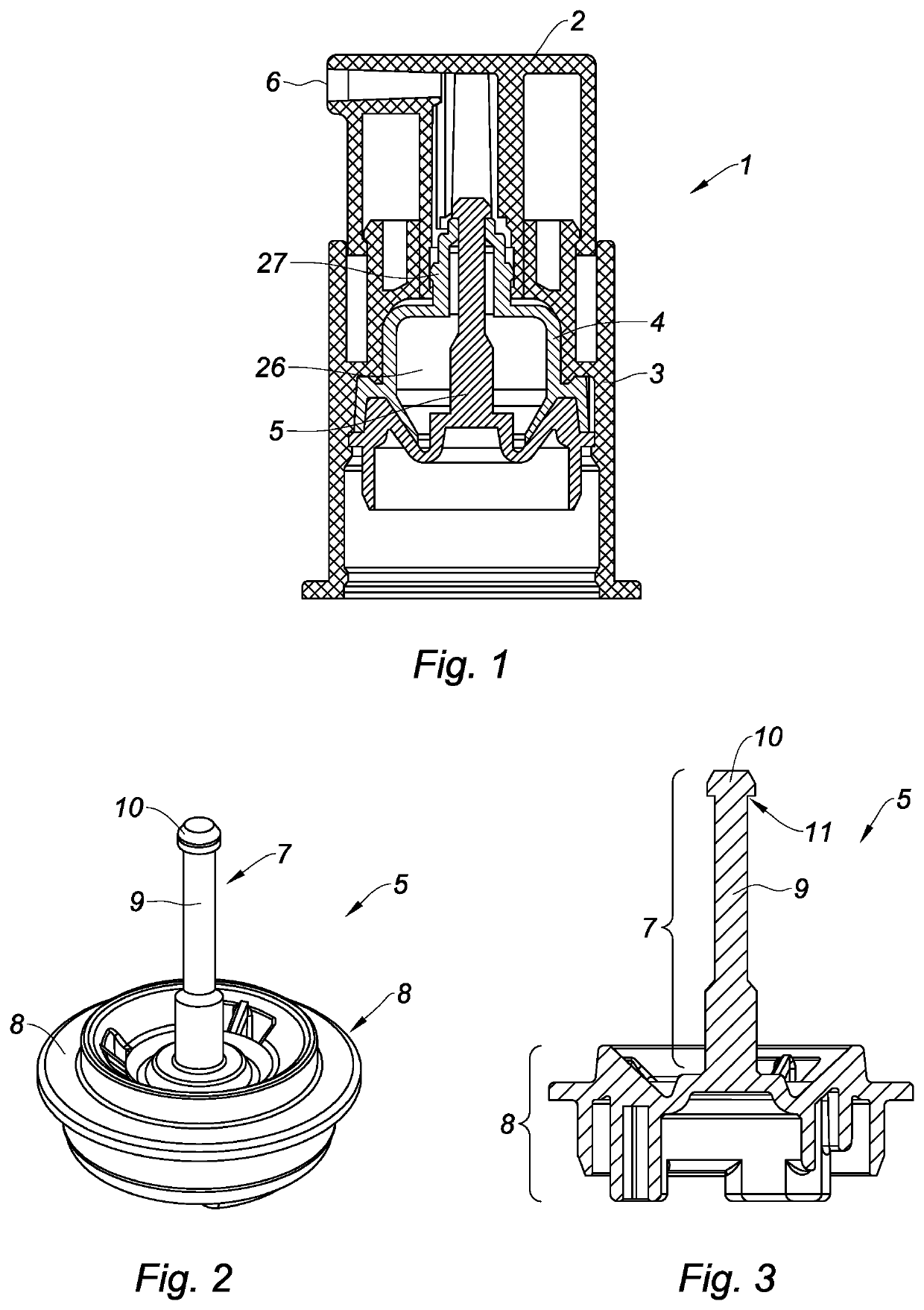
[0038]FIG. 1 shows a pump 1 for a container, in particular a vial intended to contain a cosmetic product. The pump 1 includes a pushbutton 2, a sleeve 3, a deformable membrane 4, and an assembly 5 formed of a rod 7 and a support 8.

[0039]The pushbutton 2 has the function of making it possible for the actuation of the pump 1 by a user. The pushbutton 2 here has a cylindrical body equipped with an opening 6 for dispensing the product and an upper supporting wall on which the user exerts a pressure to actuate the pump 1, the pushbutton 2 being inserted into the sleeve 3 during the actuation.

[0040]The pump 1 further includes a pumping chamber 26 with a variable volume defined at least partially by the deformable membrane 4. The pump 1 functions by making the volume of the chamber 26 vary, by elastically deforming the membrane 4 between an initial state in the shape of a dome represented in FIG. 1, wherein the chamber 26 has a maximum volume, and a deformed state (not represented), wherei...


PUM

PropertyMeasurementUnit
Pressureaaaaaaaaaa
Diameteraaaaaaaaaa
Flexibilityaaaaaaaaaa

Abstract

The invention relates to a method for producing a guiding rod for a pump for dispensing a fluid product. The rod includes a cylindrical body surmounted by a head. The method a plastic injection molding step to form the cylindrical rod. The method also includes a step of correcting the shape of an upper end of the rod so as to form the head by creating a shoulder at the level of the junction between the head of rod and body.

Description

CROSS REFERENCE TO RELATED APPLICATIONS[0001]This application claims priority under 35 U.S.C. § 119(a) to French Patent Application Serial Number 1854672, filed May 31, 2018, the entire teachings of which are incorporated herein by reference.BACKGROUND OF THE INVENTIONField of the Invention[0002]The invention relates to a method for producing a guiding rod for a pump for dispensing a fluid product, in particular used in a cosmetic product vial.Description of the Related Art[0003]Certain cosmetic product vials are provided with a pump configured to suction the cosmetic product contained in the tank of the vial in order to dispense it, for example by means of a nozzle or by a simple opening. The product can thus be extracted or sprayed from the vial in order to allow its application. The pump is often actuated by means of a pushbutton on which the user exerts a pressure to trigger the functioning of the pump. A pump includes, in particular, a pumping chamber, of which the volume varie...

Claims


Application Information

Patent Timeline
IPC IPC(8): B05B15/30
CPCB29C45/261B05B15/30B05B9/047B05B11/048B29C45/14B29C45/0055B29L2031/7496B29C2043/026B29C2043/029B29C2043/525B29C2045/0037B29C2793/0054B29C2793/0063B29C2793/009B29L2031/56B29C2045/0058B29C43/02B05B11/1028B29C45/26B29C43/021B29C43/027B05B11/042B29L2031/06
Inventor ROSSIGNOL, ERIC
Owner SILGAN DISPENSING SYST LE TREPORT
Why Eureka
Try Eureka