Layered heat exchangers

a heat exchanger and layer technology, applied in indirect heat exchangers, refrigeration components, light and heating apparatus, etc., can solve the problem of lower side walls, achieve high resistance to pressure, reduce stress concentration, and increase limit strength

Inactive Publication Date: 2005-07-26
KEIHIN THERMAL TECH CORP
View PDF15 Cites 7 Cited by
  • Summary
  • Abstract
  • Description
  • Claims
  • Application Information

AI Technical Summary

Benefits of technology

[0076]As described above, with the fluid turn portion of the layered heat exchanger of the present invention, which is designed to cause a fluid to flow zigzag through the entire interior of the layered heat exchanger, the metal plate is provided at one of the upper end and the lower end of the partition ridge with a fluid flow direction changing passage forming caved portion having a bottom wall of circular-arc cross section, the front and rear upper tank portions of the flat tube portion or the front and rear lower tank portions thereof being held in communication with each other through a fluid flow direction changing passage having an approximately circular cross section and formed by the caved portions which are opposed to each other. In the case of the present invention, the fluid flow direction changing passage is made narrower by the opposed bottom walls of a circular-arc cross section and is consequently formed by side wall portions which have a diminished area and are reinforced by the bottom walls of circular-arc cross section. At the fluid flow direction changing passage, i.e., the turn portion, the tank side walls can be given an increased limit strength against the internal pressure of the refrigerant to diminish the concentration of stress on the turn portion due to the fluid internal pressure, give the turn portion sufficiently high resistance to pressure and effectively prevent the tank side walls from breaking. This entails the advantage of making it possible to decrease the thickness of the plates providing the heat exchanger, to assure a high heat exchange efficiency and to achieve a cost reduction by the decreased thickness of the metal plates.
[0077]The bottom wall, circular-arc in cross section, of the caved portion for forming the fluid flow direction changing passage is given a smaller depth than the tank forming recessed portions to ensure the above advantage more reliably.

Problems solved by technology

Thus the heat exchanger has the problem that the tank side walls are lower than the other portions in limit strength against the internal pressure of the refrigerant.

Method used


Image

  • Layered heat exchangers
  • Layered heat exchangers
  • Layered heat exchangers

Examples


first embodiment

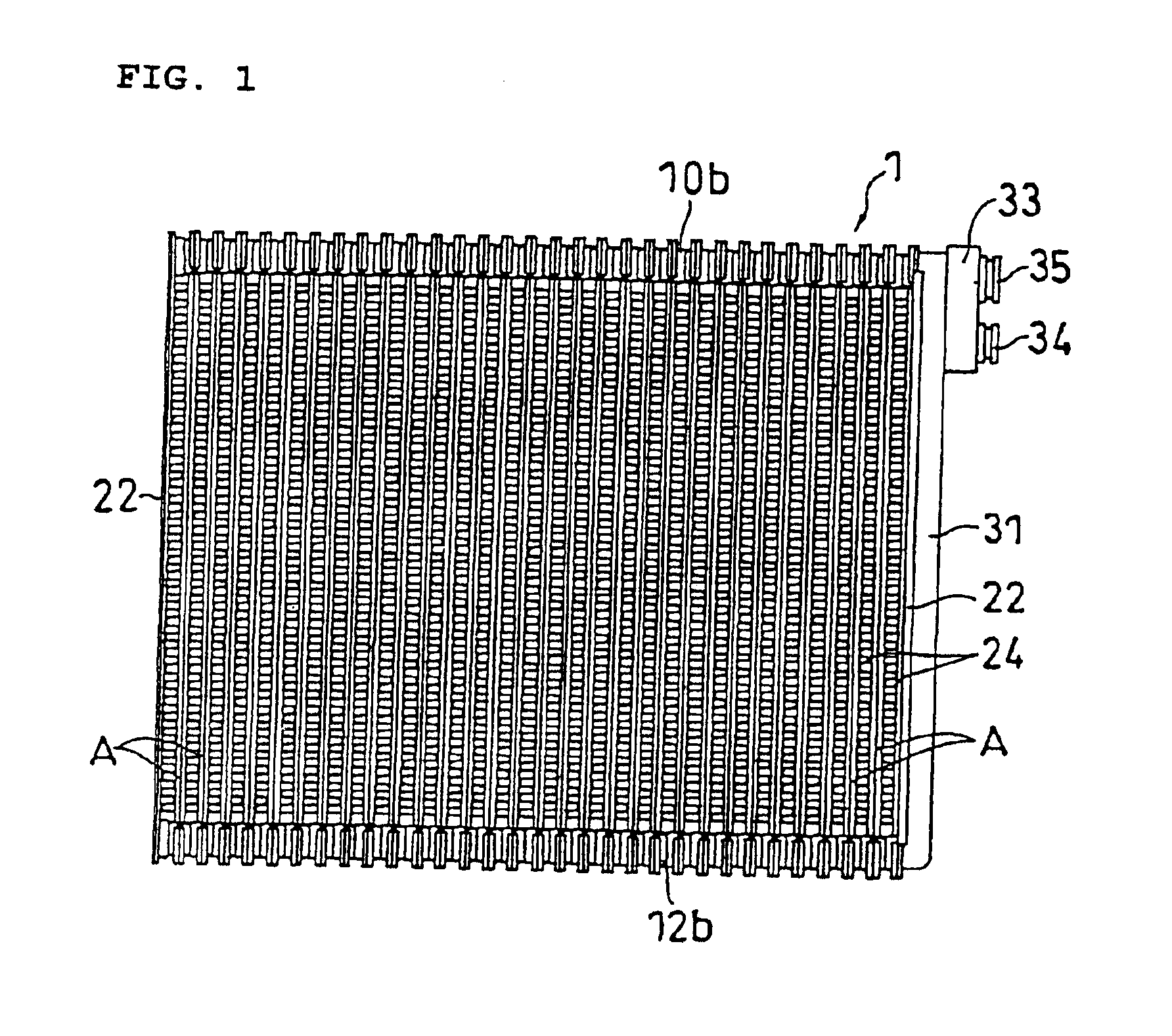
[0018]FIGS. 1 to 11 show layered evaporator of the present invention. First with reference to FIG. 1, the layered evaporator 1 of the invention is made from aluminum (including aluminum alloys), comprises a multiplicity of flat tube portions A arranged side by side, and has a refrigerant circuit which is designed to cause a refrigerant to flow zigzag through the entire interior of the evaporator 1.

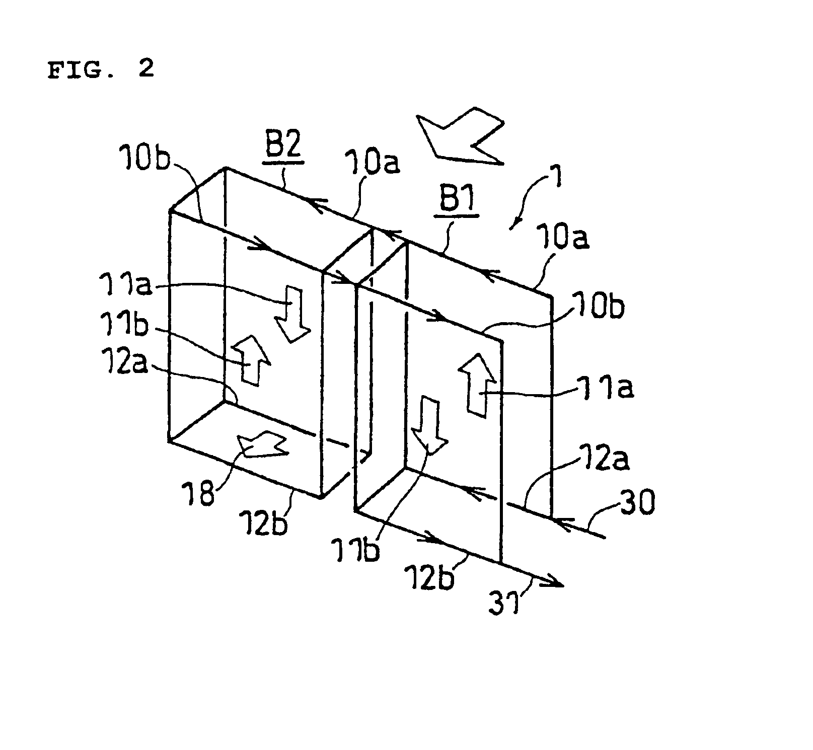
[0019]With reference to FIG. 2 showing the first embodiment, the entire assembly of many flat tube portions A is divided into left and right two flat tube blocks B1, B2. Each of the blocks B1, B2 has a plurality of flat tube portions A. The refrigerant circuit is four in the number of passes, causing the refrigerant to flow upward and downward through the two blocks B1, B2 along a total of four front and rear flat channels 11a, 11b. In this case, the left block B2 of the refrigerant circuit has a turn portion 18 for changing the direction of flow of the refrigerant from the front lower tan...

second embodiment

[0050]Stated more specifically with reference to the second embodiment, a refrigerant inlet pipe 30 is connected to the right end of the front upper tank portion 1a of the right block B1 of the evaporator 1, and a refrigerant outlet pipe 31 is connected to the right end of the rear upper tank portion 10b of the right block B1. The left end of the front and rear upper tank portions 10a, 10b of the right block B1, and the right end of the front and rear upper tank portions 10a, 10b of the left block B2 adjacent to the block B1 are provided with partition walls 8, 8 (see FIG. 5) and are closed therewith. On the other hand, apertures 15a, 15b (see FIG. 3) for passing the refrigerant therethrough are formed in the left end of the front and rear lower tank portions 12a, 12b of the right block B1, and in the right end of the front and rear lower tank portions 12a, 12b of the left block B2 adjacent to the block B1.

[0051]Furthermore, the left flat tube block B2 of the refrigerant circuit has...

third embodiment

[0053]FIG. 13 shows the present invention, i.e., a layered evaporator 1 having a refrigerant circuit which is five in the number of passes.

[0054]According to the third embodiment, an assembly of many flat tube portions A providing the evaporator 1 comprises a front half and a rear half which are different in the number of component blocks. The front half of the evaporator 1, which includes front upper tank portions 10a, front flat channels 11a and front lower tank portions 12a, is divided into three blocks B1, B2, B3, whereas rear upper tank portions lob, rear flat channels 11b and rear lower tank portions 12b is divided into two blocks B4, B5. The evaporator 1 in its entirety is five in the number of passes.

[0055]A refrigerant inlet pipe 30 is connected to the beginning end of the front lower tank portion 12a of the right front first block B1 of the evaporator 1. A refrigerant outlet pipe 31 is connected to the rear upper tank portion 10b of the right rear fifth block B5.

[0056]The ...


PUM


Abstract

A layered heat exchanger, for example for use for motor vehicle coolers. To provide a turn portion in the heat exchanger for changing flow direction of a fluid flowing zigzag through a fluid circuit, a metal plate is provided at the upper or lower ends of a partition ridge with a fluid flow direction changing passage forming caved portion having a bottom wall of circular-arc cross section. Front and rear upper or lower tank portions are held in communication with each other through a fluid flow direction changing passage of approximately circular cross section and formed by the caved portions opposed to each other. The turn portion is diminished in stress concentrated thereon due to fluid internal pressure and given an increased resistance to pressure to effectively prevent tank side walls from breaking, consequently making it possible to decrease the metal plates thicknesses, to achieve a cost reduction by the decreased thickness and to assure an improved heat exchange efficiency.

Description

DETAILED DESCRIPTION OF THE INVENTION[0001]1. Technical Field of the Invention[0002]The present invention relates to layered heat exchangers, for example, for use as layered evaporators for motor vehicle coolers.[0003]2. Prior Art[0004]FIGS. 17 and 18 show part of an aluminum plate for use in fabricating an aluminum layered heat exchanger for use as a conventional evaporator for motor vehicle coolers.[0005]With reference to these drawings, the aluminum plate 40 conventionally has formed in one surface thereof front and rear fluid channel forming recessed portions 42a, 42b divided by a vertically elongated partition ridge 41, front and rear upper tank forming recessed portions 43a, 43b continuous with the upper ends of these portions 42a, 42b and having a larger depth than these portions, and front and rear lower tank forming recessed portions (not shown) continuous with the lower ends of these portions 42a, 42b and having a larger depth than these portions. The front and rear upper ...

Claims


Application Information

Patent Timeline
Patent Type & Authority Patents(United States)
IPC IPC(8): F28F27/02F28F27/00F28D1/02F28D1/03F25B39/02
CPCF28D1/0341F28F9/026F25B39/022F28F2225/08
Inventor HIGASHIYAMA, NAOHISA
Owner KEIHIN THERMAL TECH CORP
Why Eureka
Try Eureka