Valve pin guide for a valve-gated nozzle

a valve gate and valve pin technology, applied in the field of injection molding apparatus, can solve the problems of poor quality parts, damaged valve pins or gate parts, and high cost of replacement and time-consuming

Inactive Publication Date: 2005-07-26
MOLD MASTERS 2007
View PDF96 Cites 32 Cited by
  • Summary
  • Abstract
  • Description
  • Claims
  • Application Information

AI Technical Summary

Benefits of technology

[0010]In a third aspect, the invention is directed to an injection molding apparatus. The injection molding apparatus includes a mold cavity block, an injection nozzle, a valve pin and a valve pin guide. The mold cavity block defines a mold cavity therein. The mold cavity has a gate. The mold cavity block has a first bore and a second bore. The gate is positioned in the second bore. The first bore is larger in diameter than the second bore. A melt channel is defined in the injection nozzle to convey melt towards the gate. The valve pin is positioned at least partially in the melt channel and is movable to control melt flow into the gate. The valve pin guide is adapted to receive and guide the valve pin into alignment with the gate. The valve pin guide is positioned in the first bore.

Problems solved by technology

When a misaligned valve pin is moved to close a gate, the valve pin collides with the gate and can cause scoring of the sealing surfaces on the valve pin and / or the gate.
This can ultimately result in poor quality parts with blemishes around the gate, and can cause other problems with the molding operation.
Furthermore, a damaged valve pin or gate can be expensive and time consuming to replace.
The damage may happen immediately, or alternatively it may happen gradually, over many cycles of opening and closing the valve pin.
Furthermore, the presence of such guide means in the nozzle melt channel typically renders more difficult a cleanout of the nozzle melt channel, hampering for example the changeover of a machine to run a new melt.
However, because a substantial portion of the nozzle melt channel is offset from the center of the nozzle, the heat distributed to the melt flowing therethrough is uneven, which can cause difficulties in controlling melt temperature.
Other problems also exist, which originate from the manufacture of the nozzles themselves instead from the properties of the melt flow.
Manufacturing errors may exist in the nozzles, which can introduce a misalignment between the valve pin and the gate that is ‘built-in’.
The guide means that are described above, which are built into the nozzle itself, do nothing to correct this particular cause of misalignment.

Method used


Image

  • Valve pin guide for a valve-gated nozzle
  • Valve pin guide for a valve-gated nozzle
  • Valve pin guide for a valve-gated nozzle

Examples


first embodiment

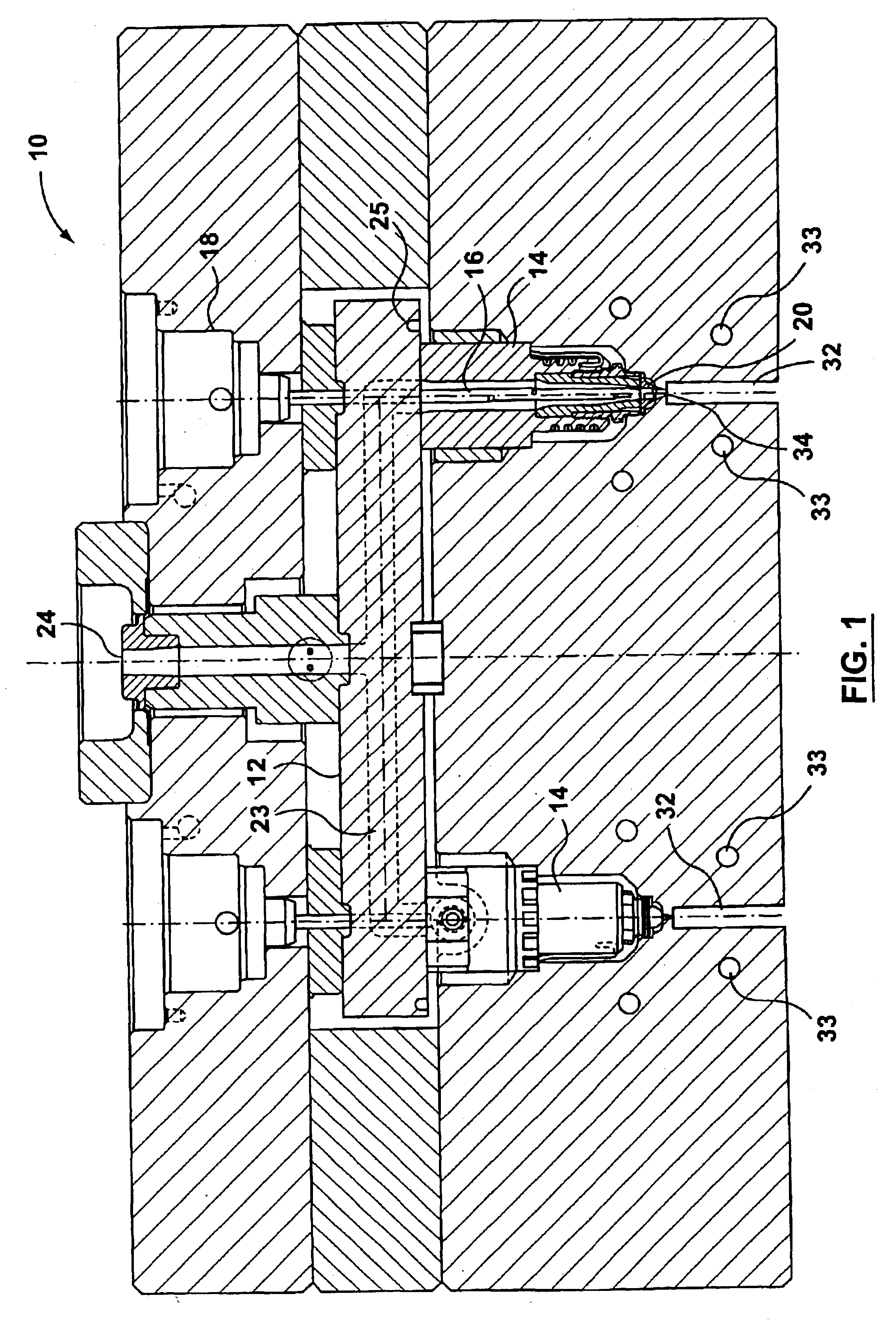
[0040]Reference is made to FIG. 1, which shows an injection molding apparatus 10, having a manifold 12, a plurality of nozzles 14, valve pins 16, valve pin actuators 18, a plurality of valve pin guides 20 in accordance with the present invention, and a mold cavity block 22.

[0041]Manifold 12 includes a plurality of runners 23 (also known as melt channels), which have an inlet 24, which receives melt from a melt source (not shown), and transport the melt to the nozzles 14. Manifold 12 may be heated by a heater 25.

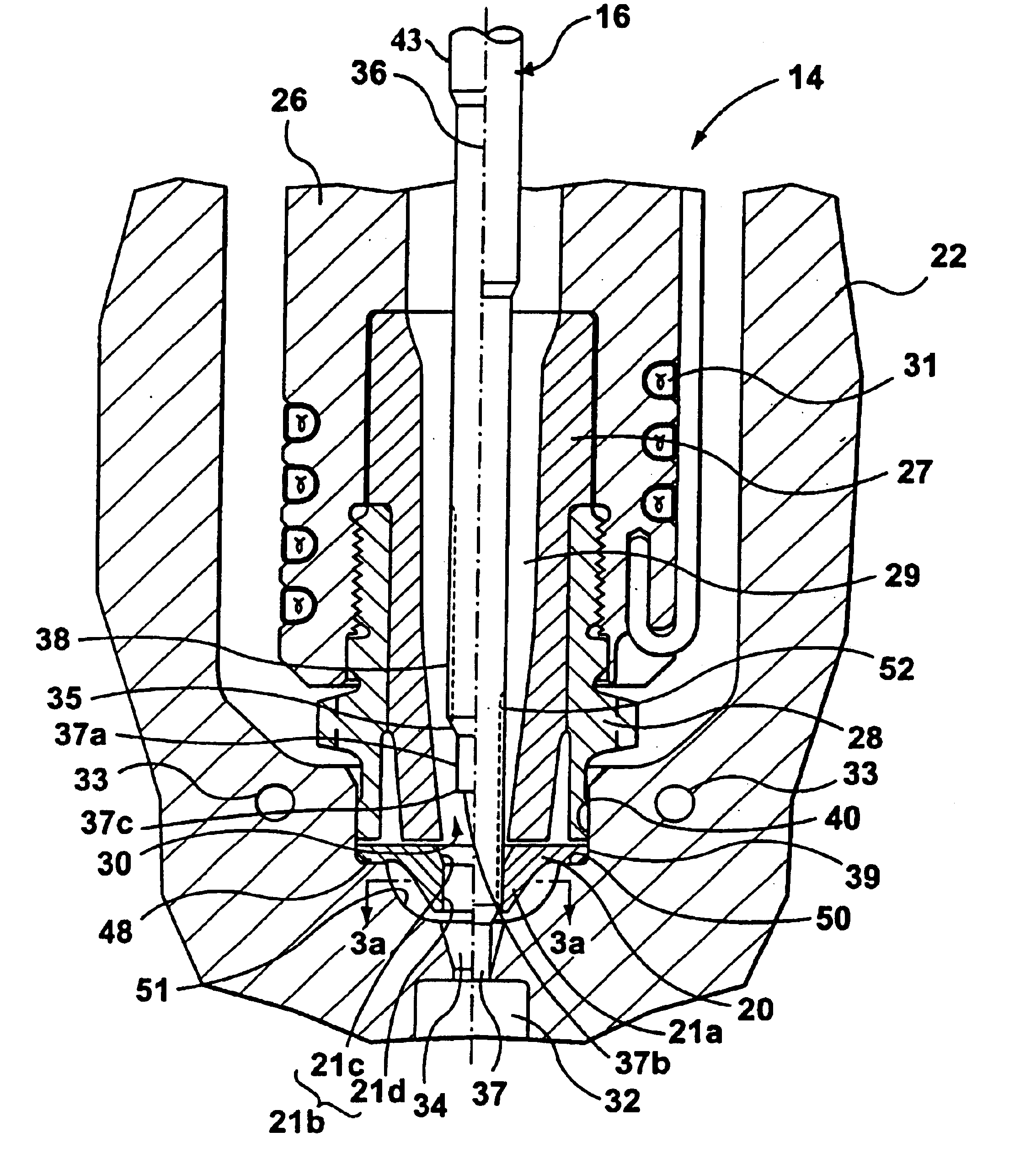
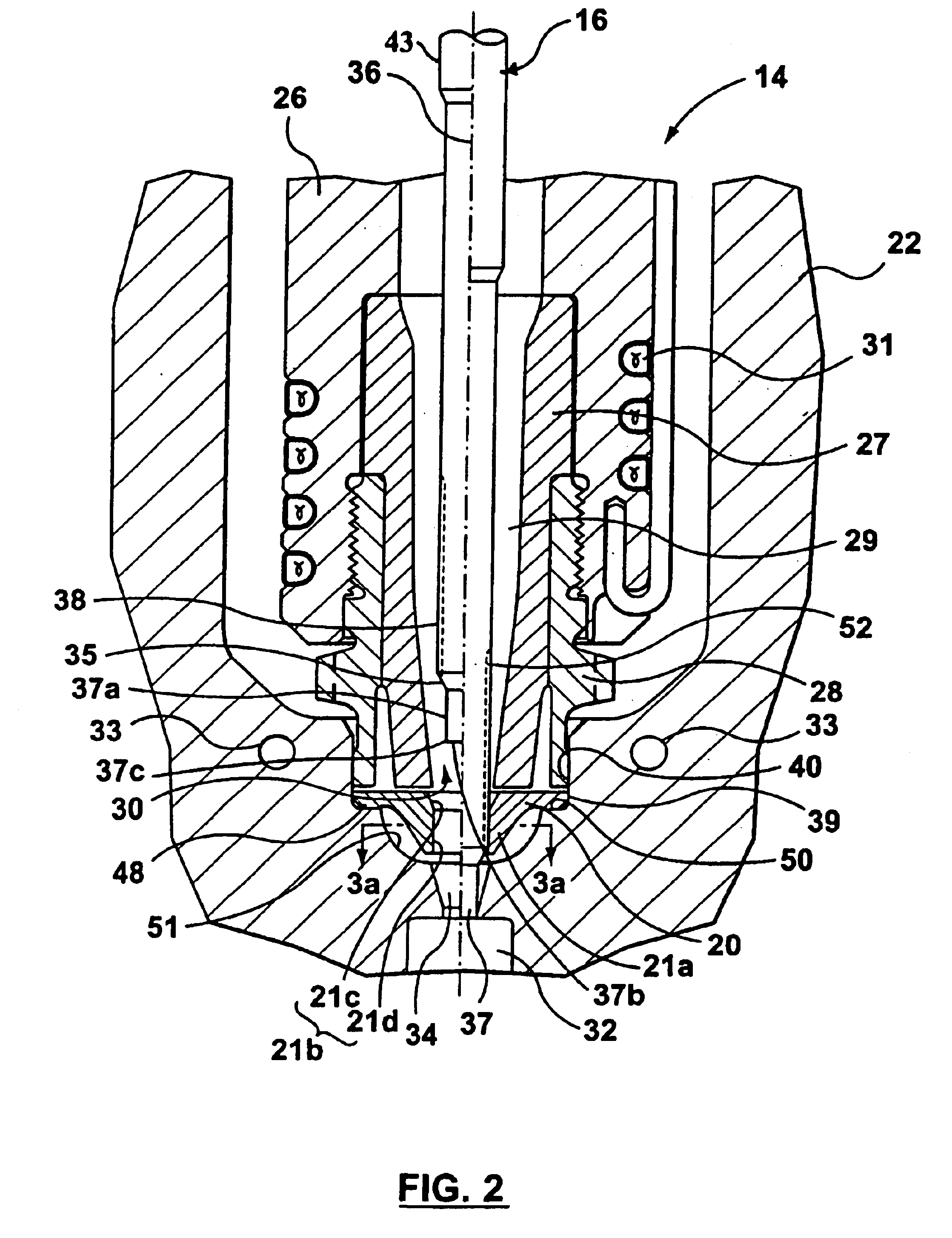
[0042]Reference is made to FIG. 2. Each nozzle 14 has a nozzle body 26. The nozzles 14 may have a separate tip 27, and may further have a separate tip retainer 28. The nozzles 14 each have a nozzle melt channel 29 that extends therethrough to transport melt from the manifold 12 to an outlet 30. Each nozzle 14 may have a heater 31, which may be any suitable type of nozzle heater. For example, the heater 31 may be a wrapped wire heater, such as is shown in FIG. 2.

[0043]The tip ...

second embodiment

[0074]Reference is made to FIG. 4, which shows a valve pin guide 100 in accordance with the present invention. Valve pin guide 100 is similar to valve pin guide 20, (FIG. 2) except that valve pin guide 100 includes a lip 102 that extends from its upper surface which is shown at 104. The lip 102 slidably mates with a vertical wall of the nozzle tip 27, facilitating heat transfer between the tip 27 and the valve pin guide 100. The heat transfer permits the valve pin guide 100 to heat melt flowing through the guide aperture 21b. By configuring lip 102 to mate slidably with a vertical wall of the nozzle tip 27, the nozzle tip 27 is permitted to move towards the valve pin guide 100 during thermal expansion of the nozzle 14 when the nozzle 14 is heated.

[0075]In this embodiment, the valve pin guide 100 may be made from a thermally conductive material, such as steel or Tungsten Carbide, in order to transfer heat from the tip 27 to the melt in the guide aperture 21b. Alternatively, as shown ...

third embodiment

[0076]Reference is made to FIG. 5, which shows a combination of the valve pin guide 20 and a hold-down spring 202, in accordance with the present invention. The hold-down spring 202 is positioned between the upper surface of the valve pin guide 20, which is shown at 204 and a shoulder 206 on the tip 27, or on any other suitable portion of the nozzle 14. Even during portions of the molding cycle when the nozzle 14 is cooler, and is therefore spaced relatively far from the valve pin guide 20, the hold-down spring 202 remains under compression and maintains a hold-down force on the valve pin guide 20, to ensure that valve pin guide 20 is held in place in the first bore 40 against shoulder 50. During portions of the molding cycle when the nozzle 14 is hotter, and has thermally expanded downwards towards the valve pin guide 20, the hold-down spring 202 flexes to account for the change in length of the nozzle 14, and continues to apply a hold-down force on the valve pin guide 20.

[0077]The...


PUM

PropertyMeasurementUnit
thermal conductivityaaaaaaaaaa
thermal expansionaaaaaaaaaa
melt flowaaaaaaaaaa

Abstract

A valve pin guide is provided for guiding a valve pin from a nozzle into a gate of a mold cavity in an injection molding apparatus. The valve pin guide defines a guide aperture therethrough. The guide aperture is adapted to receive and guide the valve pin into alignment with the gate. The valve pin guide is positioned downstream from said nozzle and upstream from said gate.

Description

FIELD OF THE INVENTION[0001]This invention relates to an injection molding apparatus, and more particularly to a guide for a valve pin in a valve-gated nozzle.BACKGROUND OF THE INVENTION[0002]It is known for a nozzle in a hot runner injection molding apparatus to include a valve pin gating mechanism at each gate into each mold cavity. The valve pin is typically moved in a melt channel of the nozzle towards or away from the gate, to control the flow of melt into the melt cavity. In order to provide a good seal at the gate, both the tip portion of the valve pin and the corresponding sealing surface on the gate must typically be machined to very close tolerances.[0003]When a misaligned valve pin is moved to close a gate, the valve pin collides with the gate and can cause scoring of the sealing surfaces on the valve pin and / or the gate. This can ultimately result in poor quality parts with blemishes around the gate, and can cause other problems with the molding operation. Furthermore, a...

Claims


Application Information

Patent Timeline
Patent Type & Authority Patents(United States)
IPC IPC(8): B29C45/28B29C45/27
CPCB29C45/278B29C45/2806B29C2045/2798B29C2045/2889
Inventor SICILIA, ROBBABIN, DENIS
Owner MOLD MASTERS 2007
Why Eureka
Try Eureka