Multi-lumen catheter with integrated connector

a multi-lumen catheter and connector technology, applied in the field of medical instruments, can solve the problems of affecting the operation of the catheter, presenting certain deficiencies, and the optimal placement of the catheter tip of the double-lumen catheter, and achieve the effect of facilitating uninterrupted catheter passag

Inactive Publication Date: 2005-07-26
TELEFLEX LIFE SCI LTD
View PDF71 Cites 170 Cited by
  • Summary
  • Abstract
  • Description
  • Claims
  • Application Information

AI Technical Summary

Benefits of technology

[0019]In order to provide distal portions of the catheter with a smooth outer profile to facilitate uninterrupted passage of the catheter through the subcutaneous tunnel, a tapered sheath may be placed around the connector and at least a portion of the adjoined flush tube portion. Preferably, the sheath includes a hollow bore for sliding engagement over the connector and flush tube portion, a tapered portion proximate to a distal end of the sheath, and a smooth outer surface. The smoothly-contoured sheath covers at least portion of the trocar shaft, the connector, and at least a portion of the flush tube portion, thereby covering and smoothing the discrete transitions between the adjoined components of the tunneling assembly. Placement of the sheath may include back-fitting the sheath over the trocar before engaging the coupling portion of the trocar in the coupling portion of the connector, and sliding the sheath over at least a portion of the trocar, the connector, and at least a portion of the flush tube portion.

Problems solved by technology

Both types, however, present certain deficiencies.
While double lumen catheters (e.g., U.S. Pat. No. 4,895,561) allow for a single venous insertion of the catheter into the desired vein, double lumen catheters typically do not permit optimal catheter tip placement.
Non-optimal tip position may significantly lower flow values, resulting in less effective dialysis treatment.
The estimated catheter tube length and subsequent forward tunneling may result in less than optimal tip placement.
Deficiencies, however, exist in this method of catheterization as well.
One problem associated with this method is that this method requires two separate venous insertions, namely, two tunnels and two of each accessory instrument used for the procedure.
During the above procedure, guiding the distal end of the catheter tube through the subcutaneous tunnel can be problematic.
Unfortunately, the frictional engagement between the trocar tip and the catheter tube may be insufficient to withstand forces exerted on the catheter tube as the tube and adjoined trocar are passed through the tunnel, thereby causing the catheter tube to loosen and separate from the trocar.
Also, because such a trocar engages only one lumen of a multi-lumen catheter, the shaft of the trocar and the catheter tube are not concentrically aligned, thereby forming a discontinuity which can impede passage of the trocar and adjoined catheter tube through the tunnel, and thereby increasing the likelihood of separation between the trocar and catheter tube.
One problems with this device included is that the connector is difficult to manipulate because of its small size.
Though this tunneling device has proven to be adequately secure in most instances, the nature of the releasable attachment does not completely eliminate the possibility that the connector may disengage from the catheter tube as the connector and tube are guided through a subcutaneous tunnel via the trocar.

Method used


Image

  • Multi-lumen catheter with integrated connector
  • Multi-lumen catheter with integrated connector
  • Multi-lumen catheter with integrated connector

Examples


embodiment 12

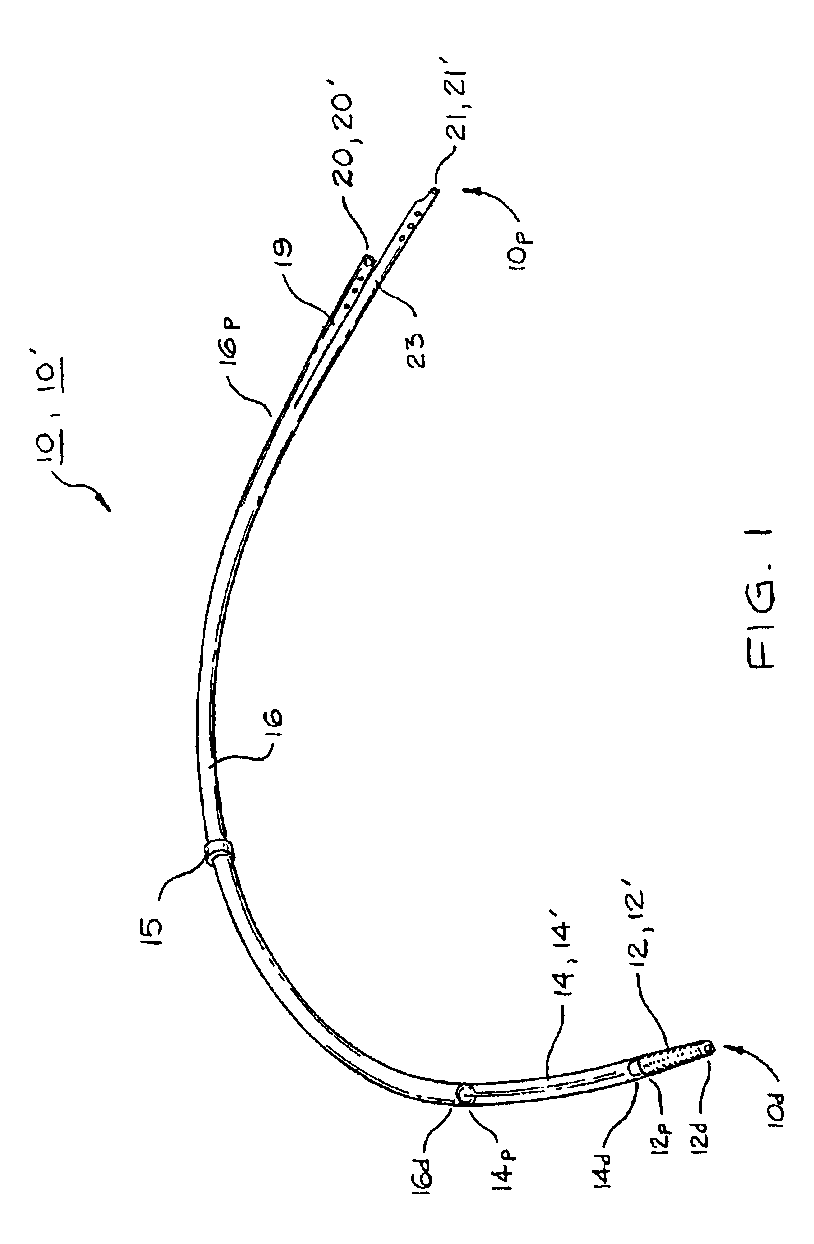
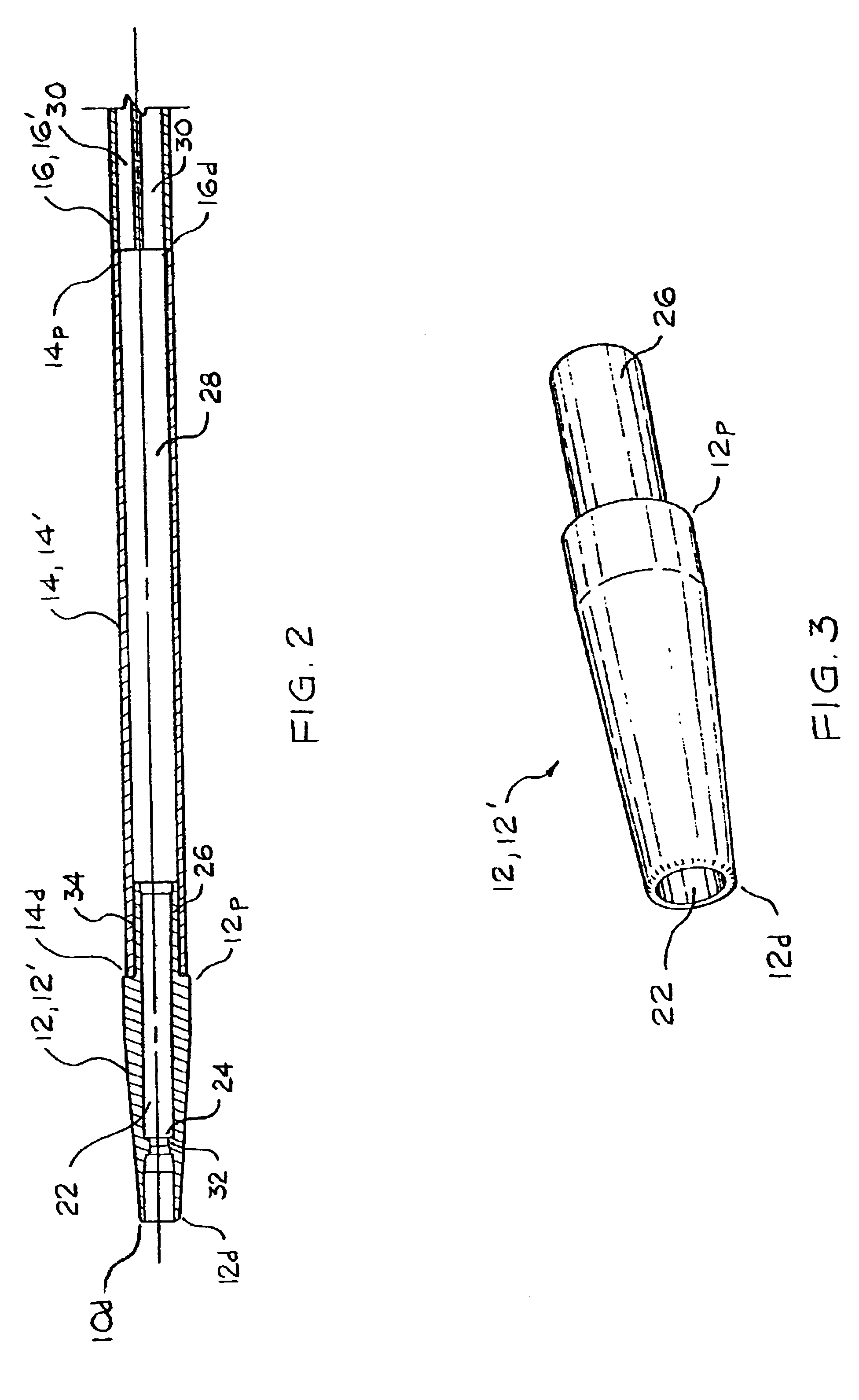
[0050]In order to permit simultaneous flushing of the multiple lumens 430, longitudinal passages 440, 442 may be provided through each of the prongs as shown in FIG. 13. Each of the passages 440, 442 is in fluid communication with a longitudinal cavity 422 in the distal end 412d of the connector 412. In this arrangement, a plurality of substantially parallel flow-paths are defined through the connector 412 from its distal end 412d to the adjoining lumens 430 in the catheter tube 416. The distal end 412d of the connector 412 may be substantially the same as the embodiment 12 of the connector as described above and shown in FIGS. 2, 3, and 6-8. For example, as shown in FIG. 13, the connector 412 may include a circumferential collar 432 in its cavity 422 for mating engagement with a trocar 40 as described above.

embodiment 10

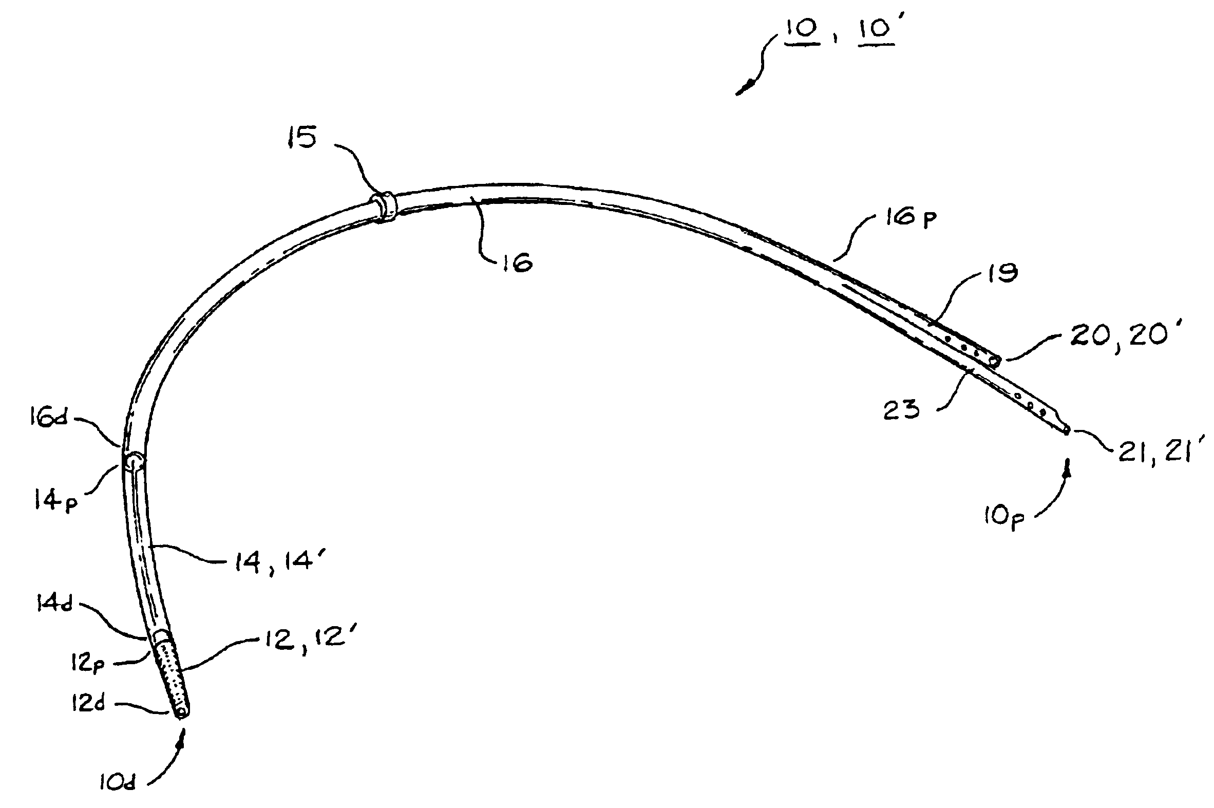
[0051]When the multi-lumen catheter tube 416 includes two lumens 430, the lumens 430, prongs 426, 427, and passages 440, 442 may have corresponding substantially D-shaped cross sections as shown in FIG. 15. In this arrangement, the D-shaped lumens 430 are separated by a divider wall or septum 460 which is received in a slot 470 between the D-shaped prongs 426, 427. A catheter 10, 410 like that described above can be used in an improved method of inserting a multiple-lumen catheter into a patient. One embodiment of such a method is sequentially illustrated in FIGS. 9A-9D. While the method is described in terms of inserting embodiment 10 of the catheter as described in detail above, the improved method can also be used for inserting alternate embodiment 410 of the multi-lumen catheter or any other similarly constructed catheter having an integrated connector on its distal end. As shown in FIG. 9A, the proximal tips 20, 21 of the catheter 10 are accurately placed in a patient's blood v...


PUM


Abstract

A multi-lumen catheter and method for inserting same into a patient is disclosed. The catheter includes a multi-lumen catheter tube having a distal end, a proximal end, and a plurality of lumens therethrough. The catheter may include a single-lumen flush tube portion, the flush tube portion having a proximal end and a distal end, the proximal end of the flush tube portion being connected to the distal end of the catheter tube such that the single lumen of the flush tube portion is in fluid communication with each of the lumens in the catheter tube. A connector is provided having a proximal end, a distal end, and a longitudinal cavity extending therethrough. The cavity includes a coupling portion near the distal end of the connector, and the proximal end of the connector is connected to the distal end of the flush tube portion or the distal end of the catheter tube such that the cavity of the connector is in fluid communication with the single lumen of the flush tube portion or the plurality of lumens in the catheter tube. The coupling portion of the cavity of the connector is configured to receive a mating coupling portion of a medical device such as a trocar. The catheter device facilitates the subcutaneous tunneling of the catheter after catheter tip placement, and simultaneous fluid communication with all of the multiple catheter lumens.

Description

BACKGROUND OF THE INVENTION[0001]1) Field of the Invention[0002]The present invention relates generally to medical instrumentation and more specifically to a multi-lumen catheter with an integrated connector that facilitates the subcutaneous tunneling of the catheter after catheter tip placement, and simultaneous fluid communication with all of the multiple catheter lumens.[0003]2) Description of the Prior Art[0004]Catheters, generally, are hollow, flexible tubes for insertion into a body cavity, duct, or vessel to allow the passage of fluids or distend a passageway. Catheters are often used for temporary or long-term dialysis treatment. Dialysis treatment provides for blood to be withdrawn from the patient, purified, and then returned to the patient. Thus, in dialysis treatment, catheters are used to allow passage of a patient's blood into and out of the patient's body. For optimal performance during dialysis treatment, the catheter tips, both in-flow and out-flow, should be placed...

Claims


Application Information

Patent Timeline
Patent Type & Authority Patents(United States)
IPC IPC(8): A61M25/00A61M31/00A61M3/00A61B17/34A61MA61M25/01A61M25/04A61M39/12
CPCA61M25/0069A61M25/0194A61M39/105A61M39/12A61M25/0028A61M25/0029A61M25/007A61M25/0097A61M2025/0019A61M2025/0031A61M2025/0037
Inventor WILSON, JON S.CASSIDY, KENNETH T.MARTEL, MARK C.
Owner TELEFLEX LIFE SCI LTD
Why Eureka
Try Eureka