Union device for dust-box in cyclone type vacuum cleaner

a technology of cyclone vacuum cleaner and dust box, which is applied in the direction of suction cleaners, cleaning filter means, reversed direction vortex, etc., can solve the problems of reducing the maximum dust collection capacity of the dust box and dropping the reliability of the product, so as to achieve the maximum possible dust collection capacity

Inactive Publication Date: 2005-08-02
LG ELECTRONICS INC
View PDF15 Cites 96 Cited by
  • Summary
  • Abstract
  • Description
  • Claims
  • Application Information

AI Technical Summary

Benefits of technology

[0008]An object of the present invention is to provide a device for fastening a dust box to a body of the cyclone vacuum cleaner, which permits smooth taking out, and putting in of a dust box.
[0009]Another object of the present invention is to provide a device for fastening a dust box to a body of the cyclone vacuum cleaner, which can maximize an allowable dust collecting capacity, and prevent escape of various foreign matters from the dust box during the dust box is taken out of the body.

Problems solved by technology

This reduces a maximum dust collecting capacity of the dust box, and causes a serious problem in keeping the room clean, that drops a reliability of the product.

Method used


Image

  • Union device for dust-box in cyclone type vacuum cleaner
  • Union device for dust-box in cyclone type vacuum cleaner
  • Union device for dust-box in cyclone type vacuum cleaner

Examples


second embodiment

[0034]FIG. 8 illustrates a disassembled perspective view of key parts showing a taking out-putting in structure formed between an accommodating part of a cyclone collector and a dust box in accordance with a second preferred embodiment of the present invention, schematically. In the present invention, a projection 111 is formed on a bottom of inside of the accommodating part 110, and the recess 331 is formed in a bottom of the dust box 330 opposite to the projection 111. The recess 331 is formed to elongate from a side insertion of the projection 111 is started along a bottom circumference of the dust box 330. And, the recess 331 is gradually sloped along a direction of rotation of the dust box 330 until the height of the slope is the same with a height of the bottom of the dust box 330.

[0035]FIG. 9 illustrates a disassembled perspective view of key parts showing a taking out-putting in structure formed between an accommodating part of a cyclone collector and a dust box in accordanc...

fourth embodiment

[0037]FIGS. 10˜12A, 12B illustrate the present invention.

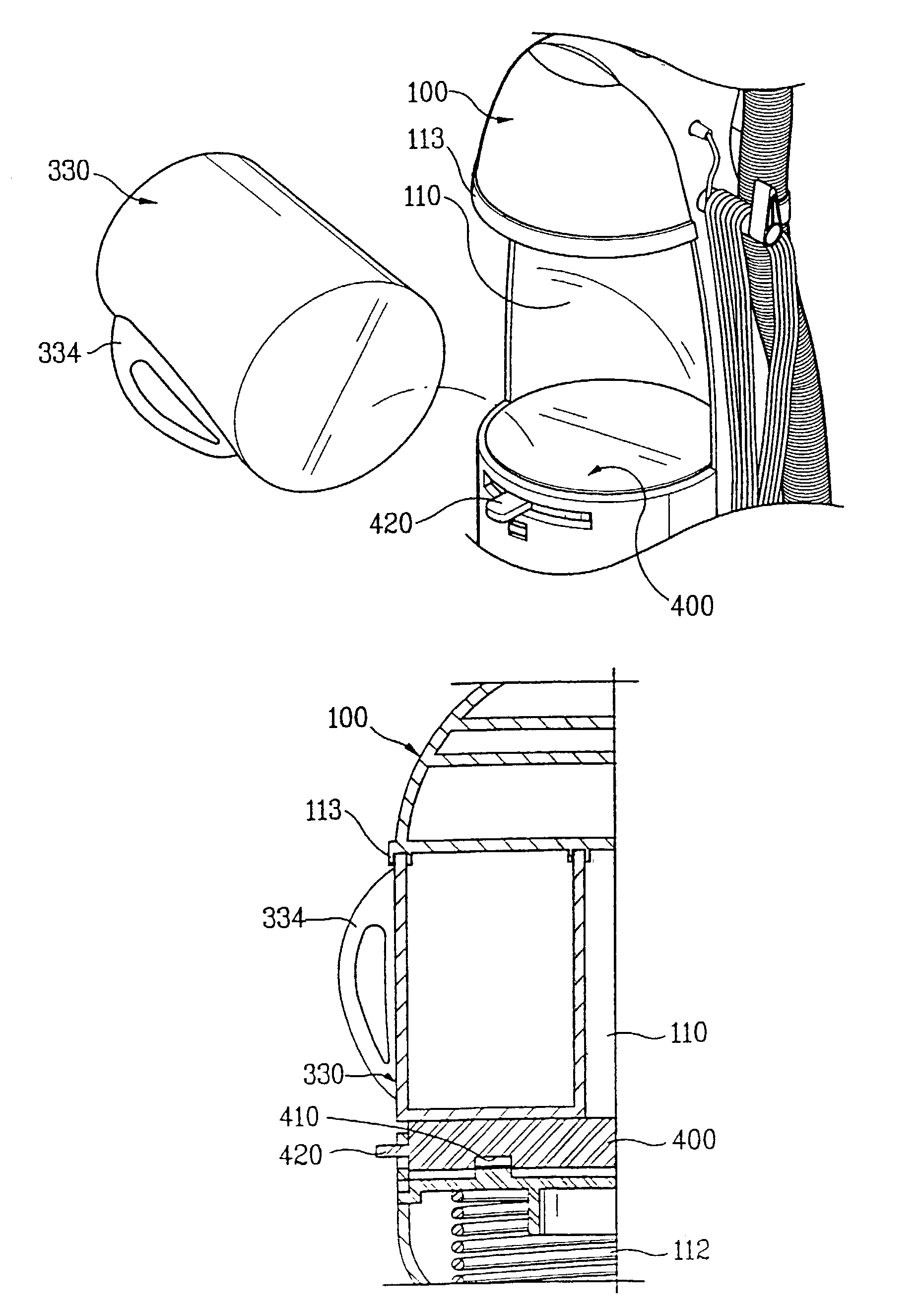
[0038]In the fourth embodiment of the present invention, the dust box 330 is put in the accommodating part 110, not by rotating the dust box 330, but by moving the dust box 330 upward by means of separate structure, and is taken out of the accommodating part 110 by moving the dust box 330 downward by means of the separate structure. In order to do this, a moving part 400 and a guide part 430 are provided for fastening and moving the dust box 330 in up and down directions in the accommodating part 110, and fastening means between a bottom of the moving part 400 and a bottom of the accommodating part 110 for moving the moving part 400 in up and down directions, selectively. The fastening means has a basic system similar to the sloped projection 111 and the recess 331 in the foregoing embodiments of the present invention. That is, projections 411 are formed on the top of the guide part 430 oppositely, and the recesses 410 are for...

fifth embodiment

[0039]FIGS. 13 and 14 illustrate the present invention.

[0040]In the fifth embodiment of the present invention, mere pushing of the dust box 330 into the accommodating part 110 completes putting in the dust box in the accommodating part. To do this, in the fifth embodiment of the present invention, projections 111 sloped gradually the more upwardly as it goes the farther toward inside of the accommodating part 110 are formed on the bottom of the accommodating part 110, and opposite projections 335 sloped gradually the more downwardly as it goes the more toward front of the accommodating part 110 are formed on the bottom of the dust box 330. In this instance, the projections 111 and the opposite projections 335 are formed at opposite positions, for making the upward or downward movement of the dust box 330 as the projections 111 and 335 are brought into contact and slide on each other. The projections 111 and 335 are formed in pair on the bottoms of the accommodating part 110 and the ...


PUM


Abstract

Device for fastening a dust box to a cyclone vacuum cleaner, including an accommodating part having a space in a body of the cyclone vacuum cleaner, a dust box mounted in the accommodating part selectively, for collecting various foreign matters separated from air, and fastening means for moving the dust box in the accommodating part in up and down directions selectively for putting, or taking the dust box into/out of the accommodating part, whereby permitting smooth putting in and taking out the dust box with simple operation, and preventing escape of various foreign matters from the dust box during putting or taking the dust box in/out of the cleaner.

Description

TECHNICAL FIELD[0001]The present invention relates to a cyclone vacuum cleaner, and more particularly, to a device for fastening a dust box to a cyclone vacuum cleaner.BACKGROUND OF THE RELATED ART[0002]The cyclone vacuum cleaner is a kind of cleaner having a cyclone collector applied to a vacuum cleaner, wherein the cyclone collector uses a cyclone action in separating and collecting various foreign matters from drawn air. As shown in FIG. 1, the cyclone vacuum cleaner is provided with a vertical body 10, and a suction nozzle body 20 fastened to a lower portion of the body 10 for drawing various foreign matters, such as dust. There is a fan coupled to a motor for generating a vacuum in the cleaner body 10 when required. And, there is an accommodating part 111 in an inside of an upper portion of the body 10 for fastening a cyclone collector which separate the various foreign matters from the air drawn through the suction nozzle body 20, and collecting the foreign matters.[0003]The c...

Claims


Application Information

Patent Timeline
Patent Type & Authority Patents(United States)
IPC IPC(8): A47L9/16A47L9/10B04C5/04B04C5/187B04C9/00
CPCA47L9/1691
Inventor JEONG, WON CHUL
Owner LG ELECTRONICS INC
Why Eureka
Try Eureka