Optical transducers and method of making same

a technology of optical transducers and optical transducers, applied in the field of optical transducers, can solve the problems of low production cost and relatively high production cost of known optical transducers, and achieve the effects of low cost, low cost and easy mass production

Inactive Publication Date: 2005-08-02
PHONE OR
View PDF6 Cites 1 Cited by
  • Summary
  • Abstract
  • Description
  • Claims
  • Application Information

AI Technical Summary

Benefits of technology

[0005]One object of the present invention is to provide an optical transducer of a novel construction which more readily permits mass production at relatively low cost. Another object of the invention is to provide a method of producing optical transducers in a manner which permits mass production at relatively low cost.
[0012]As will be described more particularly below, the foregoing features enable optical transducers to be constructed in a manner which is more efficient than prior art methods, and which also more readily lends itself to low-cost mass production.

Problems solved by technology

In general, the known optical transducers do not readily lend themselves to low-cost mass production, and therefore are relatively expense to produce.

Method used


Image

  • Optical transducers and method of making same
  • Optical transducers and method of making same
  • Optical transducers and method of making same

Examples


Embodiment Construction

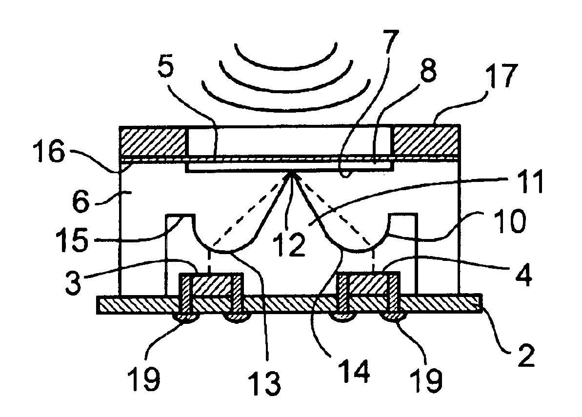
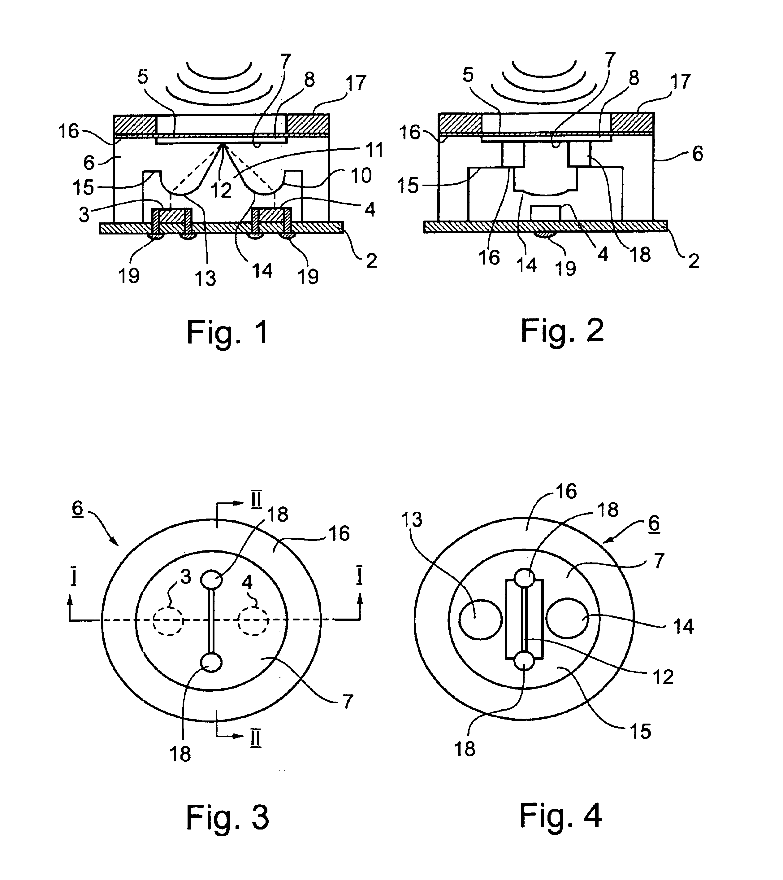
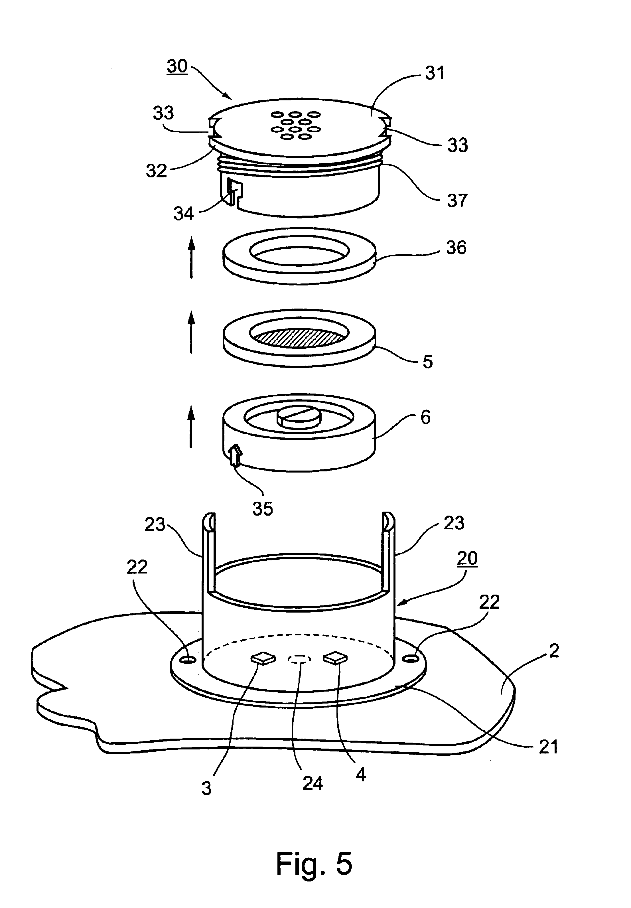
[0021]The preferred embodiment of the invention described below is based on an optical transducer of generally the same construction as described in the above-cited International Application PCT / IL02 / 00241 but modified in accordance with the present invention. Such an optical transducer includes a base member 2 mounting a light source 3 and a light detector 4 in laterally spaced relationship to each other, a deformable membrane 5 overlying the light source 3 and light detector 4, and a light transparent body 6 between the light source and light detector on one side, and the deformable membrane 5 on the opposite side. The light transparent member 6 is of generally cylindrical configuration and is formed with a central circular recess 7 on its outer surface to define a small space 8 between it and the inner surface of membrane 5.

[0022]The inner surface 10 of the light transparent body 6 facing the light source 3 and light detector 4 is shaped to direct light emanating from the light s...


PUM


Abstract

An optical transducer includes a light source and a light detector mounted on a base member in laterally spaced relation to each other, a deformable membrane overlying the light source and light detector, and a light transparent body between the light source and light detector on one side, and the deformable membrane on the opposite side, such as to direct light emanating from the light source to the membrane, and to direct light reflected from the membrane to the light detector in accordance with the deformations of the membrane. According to the described method of making the optical transducer, the light source and light detector are enclosed in a first casing closed at one end by the base member and open at the opposite end; and the light transparent body is enclosed in a second casing to be closed at one end by the deformable membrane and open at the opposite end. The two casings are attached to each other with their open ends facing each other such that the light transparent body of the second casing overlies the light source and light detector of the first casing.

Description

FIELD AND BACKGROUND OF THE INVENTION[0001]The present invention relates to optical transducers (sometimes referred to as optical sensors) which utilize optical means for sensing mechanical displacements, such as movements of a body or deformation of a membrane, and converting them to electrical signals. The invention also relates to methods of making such optical transducers. The invention is particularly useful in making optical microphones for converting sound into electrical signals and is therefore described below especially with respect to this application.[0002]Optical transducers of this type are described, for example, in U.S. Pat. Nos. 5,771,091; 5,969,838; 6,091,497; and 6,239,865, and in International Application PCT / IL02 / 00241 the contents of which patents and application are incorporated herein by reference.[0003]Such optical transducers generally include an optical unit containing a light source, a laterally spaced light detector and a displaceable member aligned with...

Claims


Application Information

Patent Timeline
Patent Type & Authority Patents(United States)
IPC IPC(8): G01D5/26G01D5/28H04R23/00
CPCG01D5/28H04R23/008
Inventor PARITSKY, ALEXANDERKOTS, ALEXANDER
Owner PHONE OR
Why Eureka
Try Eureka