System for Generating Cost-Efficient Low Emission Energy

a low-emission energy and system technology, applied in the field of energy generation, investment, environmental regulation, can solve the problems of increasing the difficulty of obtaining permits for coal-fired plants, increasing the cost of operation of coal-fired generating plants, and increasing the cost of gas-fired generating plants, so as to achieve greater emissions, reduce emissions, and create more capacity

Inactive Publication Date: 2010-12-02
HYBRID HEATING SYST LLC
View PDF6 Cites 2 Cited by
  • Summary
  • Abstract
  • Description
  • Claims
  • Application Information

AI Technical Summary

Benefits of technology

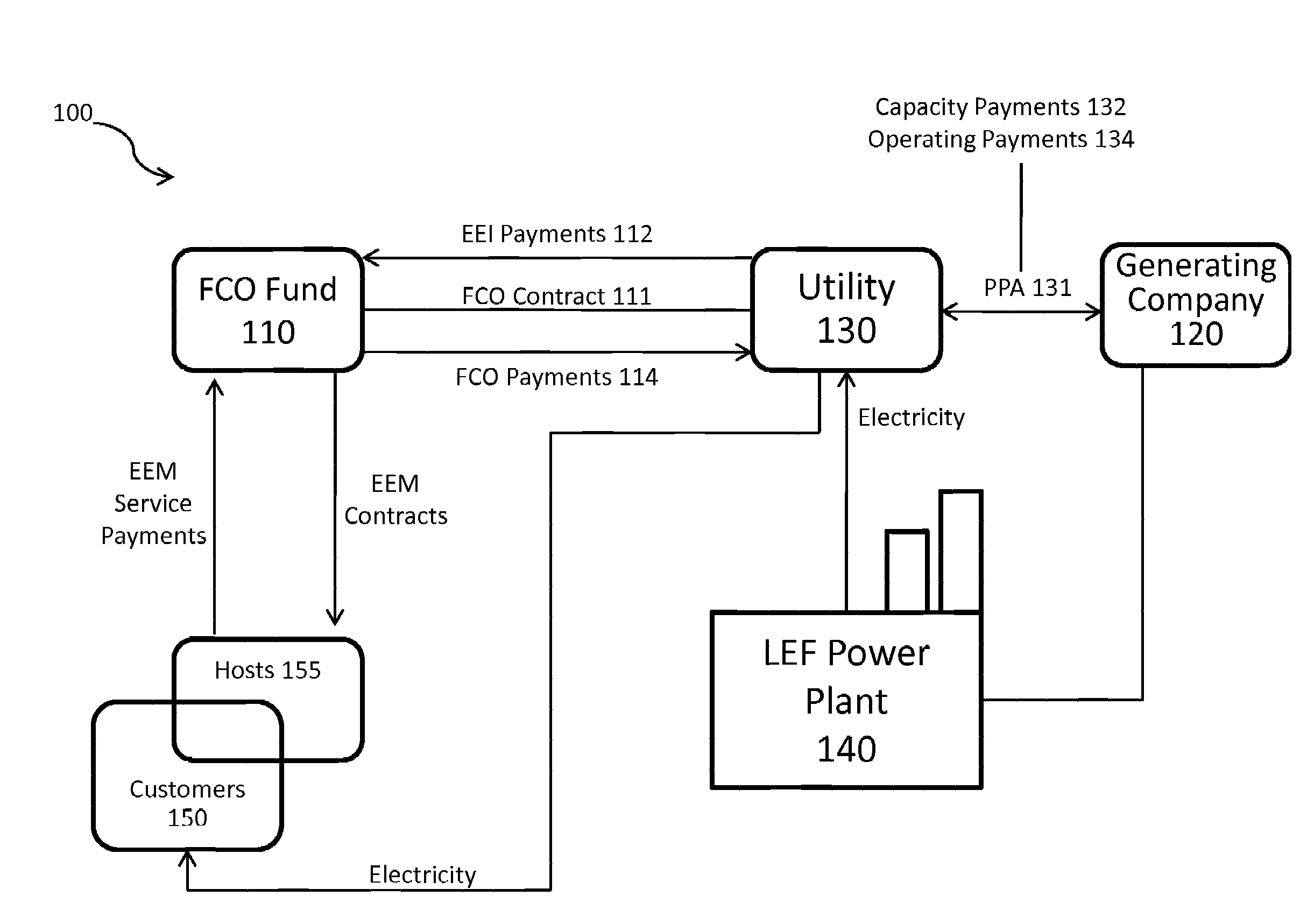
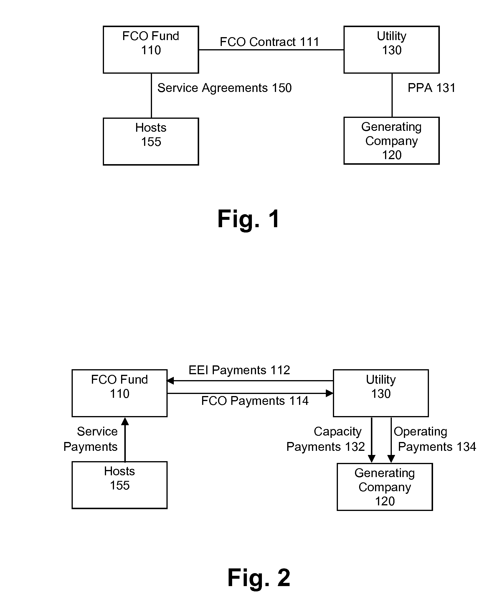
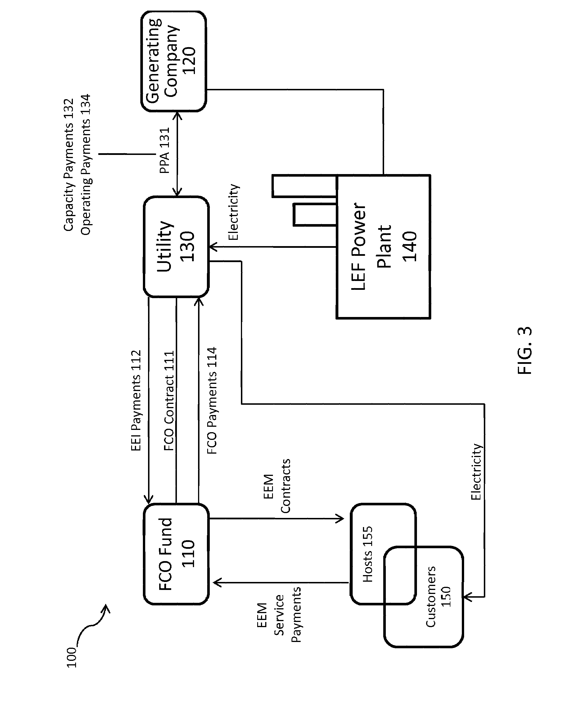
[0010]Additionally, the present system provides a method for controlling or influencing the capital decisions on whether to build or upgrade a facility to create more capacity or to reduce emissions. By using a DCD arrangement, the excess capacity of under-utilized low emission fuel facilities can be used to offset the capacity of a facility that creates greater emissions than the low emission fuel facility. By using the underutilized capacity in an economical manner, the utility may be able to replace the capacity of a coal or oil burning facility without building new capacity.
[0011]Additionally, the present system provides a method which can lead to the increased implementation of EEMs. The present system provides a method for providing capital that ...

Problems solved by technology

Coal plants are a preferred power source due to low and non-volatile fuel costs; however, concerns with the emission of significant air pollutants are making coal-fired plants increasingly difficult to permit and the requirement to fund emissions compliance measures are making coal-fired plants increasingly expensive to operate.
Natural gas-fired generati...

Method used


Image

  • System for Generating Cost-Efficient Low Emission Energy
  • System for Generating Cost-Efficient Low Emission Energy
  • System for Generating Cost-Efficient Low Emission Energy

Examples


example

[0038]In the following example, the system is described in connection with a particular type of low emission fuel power plant, namely a gas-fired power plant, such as a natural gas-fired combined cycle gas turbine (CCGT). However, it should be understood the gas-fired plant is simply an example of a reduced emission electrical generation facility. As such, the present system is not limited to a system that utilizes a gas-fired power plant. Additionally, a coal-fired plant is used as a base load electricity generation plant having normal emissions. However, it should be understood that the coal-fired plant is just an example of an electricity generation facility that produces increased emission relative to an LEF power plant

[0039]The example below compares the capital cost and operating expenses of a typical 750 Mw coal-fired generating plant constructed with best available technology to a 750 Mw natural gas CCGT plant built in conjunction with EEMs and an FCO Fund. The assumptions u...


PUM


Abstract

A method of economically substituting higher-priced clean energy sources for lower-price energy sources with negative environmental attributes by using a portion of the return on investment in a portfolio of residential, commercial, institutional or industrial energy efficiency measures to offset the cost of higher-priced, clean energy. Proceeds from investments and the monetization of the environmental benefits of the invention would are used to subsidize the cost of natural gas-fired plants so that they can economically displace coal-fired plants or other types of plants with similar negative environmental attributes as a source for base load power generation.

Description

PRIORITY CLAIM [0001]This application claims priority to U.S. Provisional Patent Application No. 61 / 182,903, filed Jun. 1, 2009, the entire disclosure of which is hereby incorporated by reference.FIELD OF THE INVENTION [0002]The invention generally relates to the fields of energy generation, investing, and environmental regulation, and in particular to the method of using gains from an investment in energy-efficiency measures to offset the cost of power generation through natural gas combustion.BACKGROUND [0003]The electric utility industry faces a number of fundamental issues, some of which are described below. First and foremost, utilities must meet the demand for new generating capacity in the face of substantial permitting and financing challenges. Second, utilities must comply with new environmental regulations by 2015 to reduce harmful air emissions, principally from coal-fired plants. Compliance with these known regulations and pending CO2 regulations which in large measure a...

Claims


Application Information

Patent Timeline
IPC IPC(8): G06F1/26G06Q40/00G06Q50/00
CPCG06Q10/06G06Q40/04Y02E40/76Y04S10/54Y04S10/58Y02P90/90Y04S10/545Y02E40/70Y04S10/50
Inventor MILLER, STEVEN F.
Owner HYBRID HEATING SYST LLC
Why Eureka
Try Eureka