Refrigerant Dehumidification System with Variable Condenser Unloading

a dehumidification system and variable technology, applied in the field of refrigerant systems, can solve the problems of difficult control, unsatisfactory instabilities in the refrigerant circuit, and the limited range of applications of condenser bypass alone, and achieve the effect of more reheating capacity

Inactive Publication Date: 2008-09-25
CARRIER CORP
View PDF15 Cites 17 Cited by
  • Summary
  • Abstract
  • Description
  • Claims
  • Application Information

AI Technical Summary

Benefits of technology

[0006]In a disclosed embodiment of this invention, a condenser, within a refrigerant system incorporating a reheat function, has a plurality of refrigerant passages with at least some of these passages being pro

Problems solved by technology

Further, pulsating flow in the bypass line (in case pulse width modulation method is used) may introduce some undesired instabilities within the refrigerant circuit that may be dif

Method used


Image

  • Refrigerant Dehumidification System with Variable Condenser Unloading
  • Refrigerant Dehumidification System with Variable Condenser Unloading

Examples


Embodiment Construction

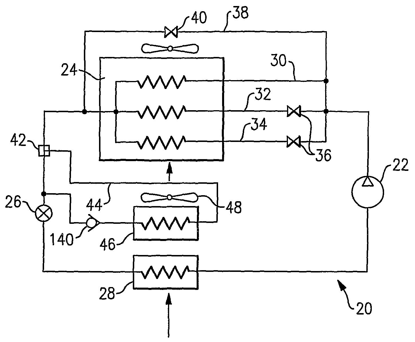
[0012]A refrigerant system 20 is illustrated in FIG. 1 including a compressor 22 compressing refrigerant and delivering it to a downstream condenser 24. An expansion device 26 is located downstream of the condenser 24, and an evaporator 28 is positioned downstream of the expansion device 26. The refrigerant returns from the evaporator 28 to the compressor 22. As shown, a number of parallel refrigerant passages (or circuits) 30, 32 and 34 pass through the condenser 24. Shutoff devices such as valves 36 are placed on two of the three circuits 32 and 34. A control operates to open or close the shutoff valves 36, as will be explained below. A bypass line 38 includes a valve 40 for selectively allowing bypass at least a portion of refrigerant around the condenser 24.

[0013]A three-way valve 42 selectively routes refrigerant into a line 44 and through a reheat heat exchanger 46. A fan 48 pulls air over the evaporator 28 and then over the reheat heat exchanger 46. Also, a check valve 140 is...


PUM


Abstract

A condenser in a refrigerant system is provided with a plurality of refrigerant circuits, with at least one of the plurality of circuits being equipped with a shut off device. A reheat coil is also incorporated into the refrigerant system to provide enhanced dehumidification functionality. By selectively shutting off at least one of the active refrigerant circuits in the condenser, the amount of heat rejected by the condenser as well as by the reheat coil can be controlled shifting the heat load between the condenser and reheat coil. In this manner, and in combination with operation of the reheat cycle, incremental dehumidification and cooling/heating can be provided and humidity and temperature can be precisely controlled.

Description

BACKGROUND OF THE INVENTION[0001]This invention relates to a refrigerant system incorporating a reheat function and a condenser comprising a number of refrigerant passages, with at least some of the passages being selectively shut off to control the total heat rejection distribution between the condenser (outdoor section) and reheat coil (indoor section).[0002]Refrigerant systems are utilized to control the temperature and humidity of air in various indoor environments to be conditioned. In a typical refrigerant system operating in the cooling mode, a refrigerant is compressed in a compressor and delivered to a condenser (or an outdoor heat exchanger in this case). In the condenser, heat is exchanged between outside ambient air and the refrigerant. From the condenser, the refrigerant is passed to an expansion device, at which the refrigerant is expanded to a lower pressure and temperature, and then to an evaporator (or an indoor heat exchanger). In the evaporator, heat is exchanged ...

Claims


Application Information

Patent Timeline
IPC IPC(8): F25D17/06F25B1/00
CPCF24F3/153F25B2400/0403F25B6/02
Inventor TARAS, MICHAEL F.LIFSON, ALEXANDER
Owner CARRIER CORP
Why Eureka
Try Eureka