Method of making a peritoneal dialysis therapy machine

a technology of peritoneal dialysis and therapy machine, which is applied in the field of automatic peritoneal dialysis systems, can solve the problems of inability to balance water, minerals and excretion of daily metabolic load, inability to excrete daily metabolic load, and inability to discharge toxic end products of nitrogen metabolism (urea, creatinine, uric acid, etc.) to achieve the effect of improving the quality of life, reducing the flexing of disposable units, and increasing rigid

Active Publication Date: 2007-09-13
BAXTER HEALTHCARE SA +1
View PDF42 Cites 79 Cited by
  • Summary
  • Abstract
  • Description
  • Claims
  • Application Information

AI Technical Summary

Benefits of technology

[0020] The manifold and other areas of the disposable unit include reduced or tapered edges that provide an area to seal the membranes. The reduced thickness or tapered area requires less heat than the full thickness, which reduces the heat sinking disparity between the thickness of the manifold of the disposable unit and the thinner flexible membranes. The frame of the manifold is bowed or curved to provide rigidity. The frame is also asymmetrical and designed to be placed into the hardware unit in only one direction.
[0048] Moreover, an advantage of the present disclosure is to provide a disposable unit having tapered interfaces that decrease the heat sinking of the semi-rigid manifold and provide a more robust seal.

Problems solved by technology

Due to disease, insult or other causes, a person's renal system can fail.
The balance of water, minerals and the excretion of daily metabolic load is no longer possible in renal failure.
During renal failure, toxic end products of nitrogen metabolism (urea, creatinine, uric acid, and others) can accumulate in blood and tissues.
Manual peritoneal dialysis performed by the patient requires a significant amount of time and effort from the patient.
This inconvenient procedure leaves ample room for improvement and therapy enhancements to improve patient quality of life.
One common problem with current home systems is that they are susceptible to electrical shock due to “leakage current”.
However, if the protective earth conductor becomes open circuited, the patient could be at risk of electrical shock.
Leakage currents are normally small, however, the amount of current required to produce adverse physiological effects in patients is also small.
Accordingly, leakage currents must be limited as much as possible by the design of the equipment and be within safety limits.

Method used


Image

  • Method of making a peritoneal dialysis therapy machine
  • Method of making a peritoneal dialysis therapy machine
  • Method of making a peritoneal dialysis therapy machine

Examples


Embodiment Construction

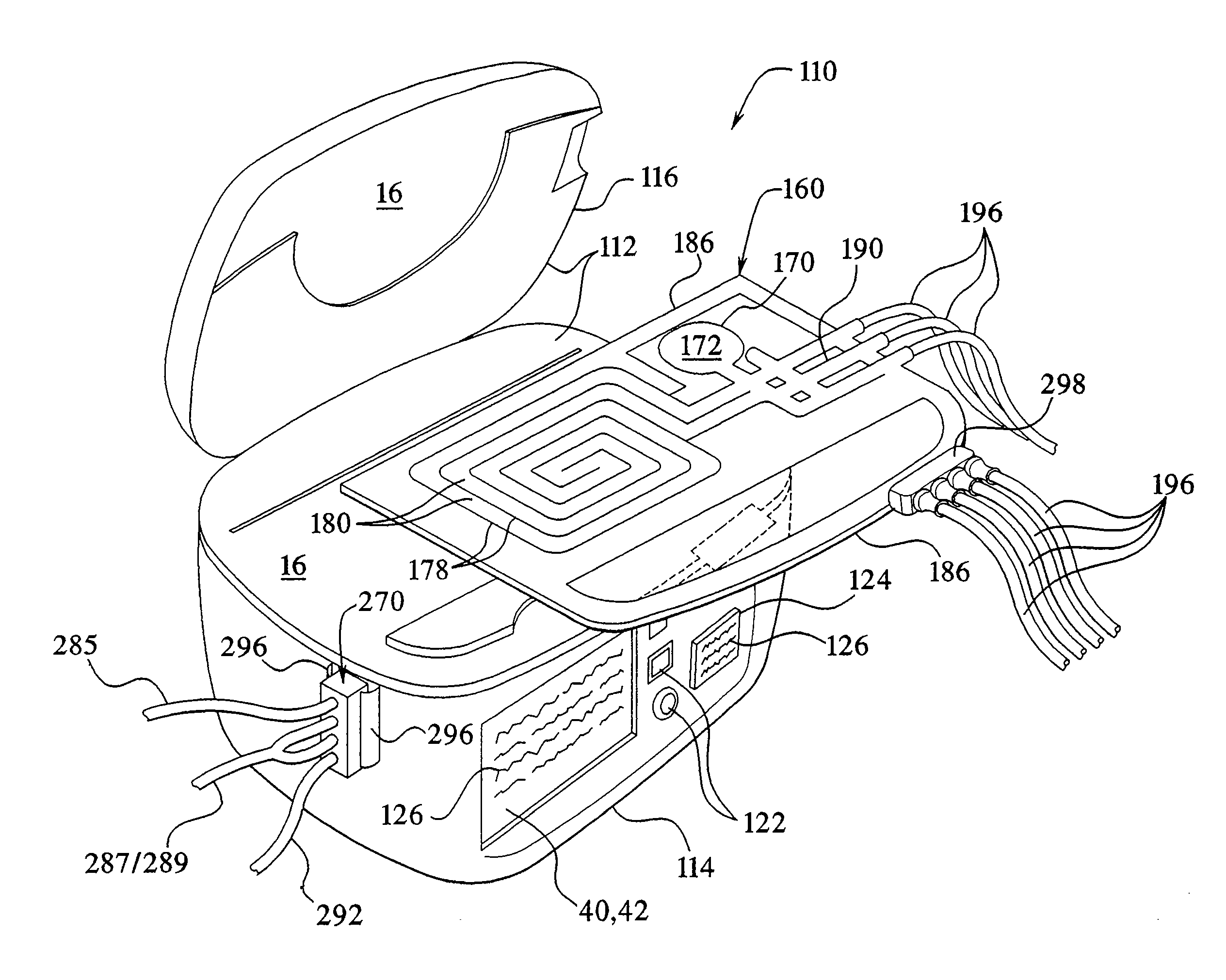
[0080] The present disclosure relates to dialysis systems and methods of performing dialysis. In particular, the present disclosure relates to a system and method for automatically providing peritoneal dialysis therapy to patients. The present disclosure provides automatic multiple exchanges of dialysis fluid to and from the patient's peritoneal cavity. The automatic exchanges of dialysate include drain, fill, and dwell periods, which usually occur while the patient sleeps. A typical therapy can include three to five exchanges of dialysis fluid. The present disclosure, in an embodiment, provides a single pass system, wherein the dialysate passes through the peritoneal cavity only once before being disposed. While the present disclosure performs peritoneal dialysis, it is also suitable for other types of dialysis and other medical fluid transfer operations.

I. The System Generally

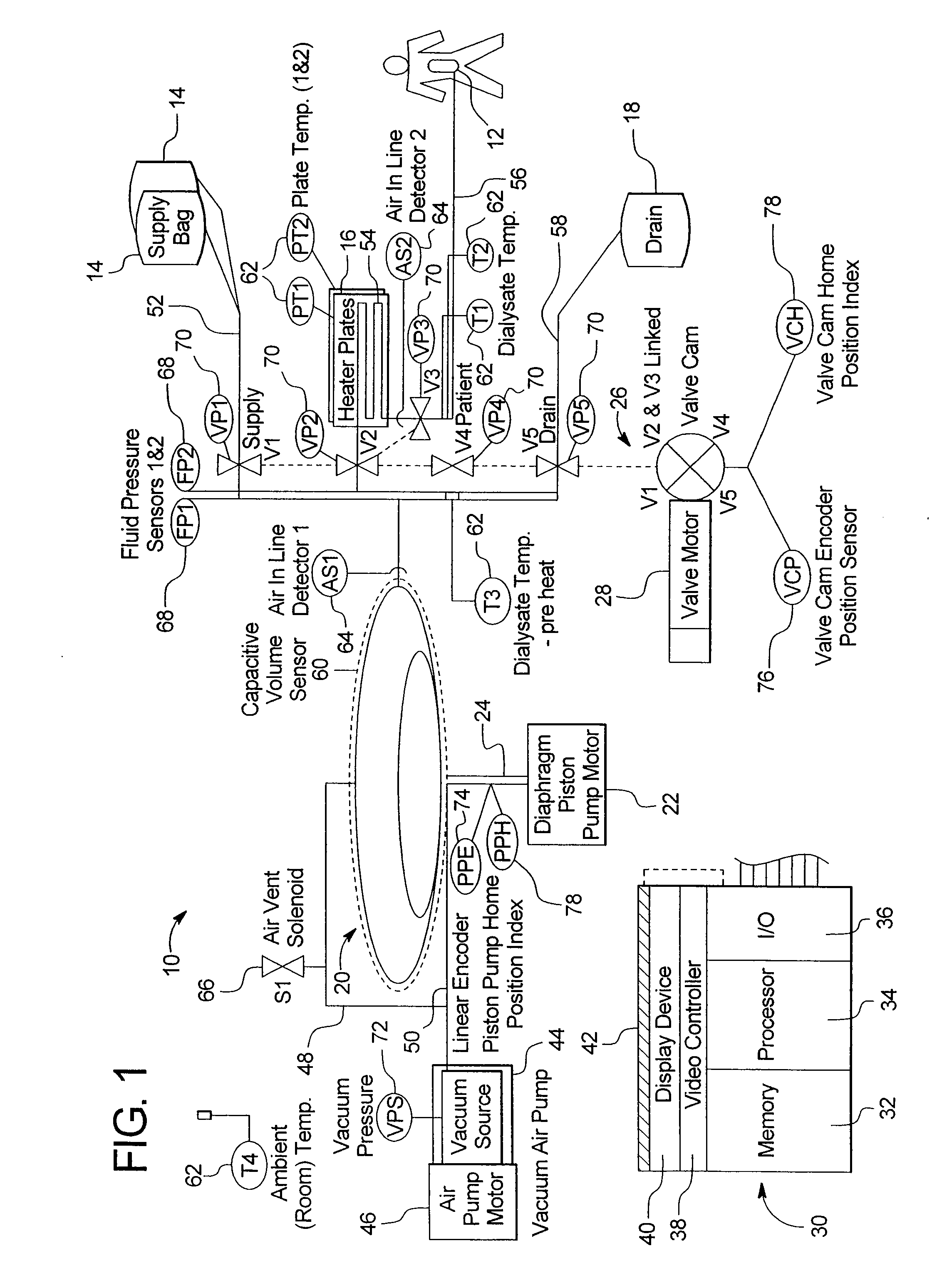
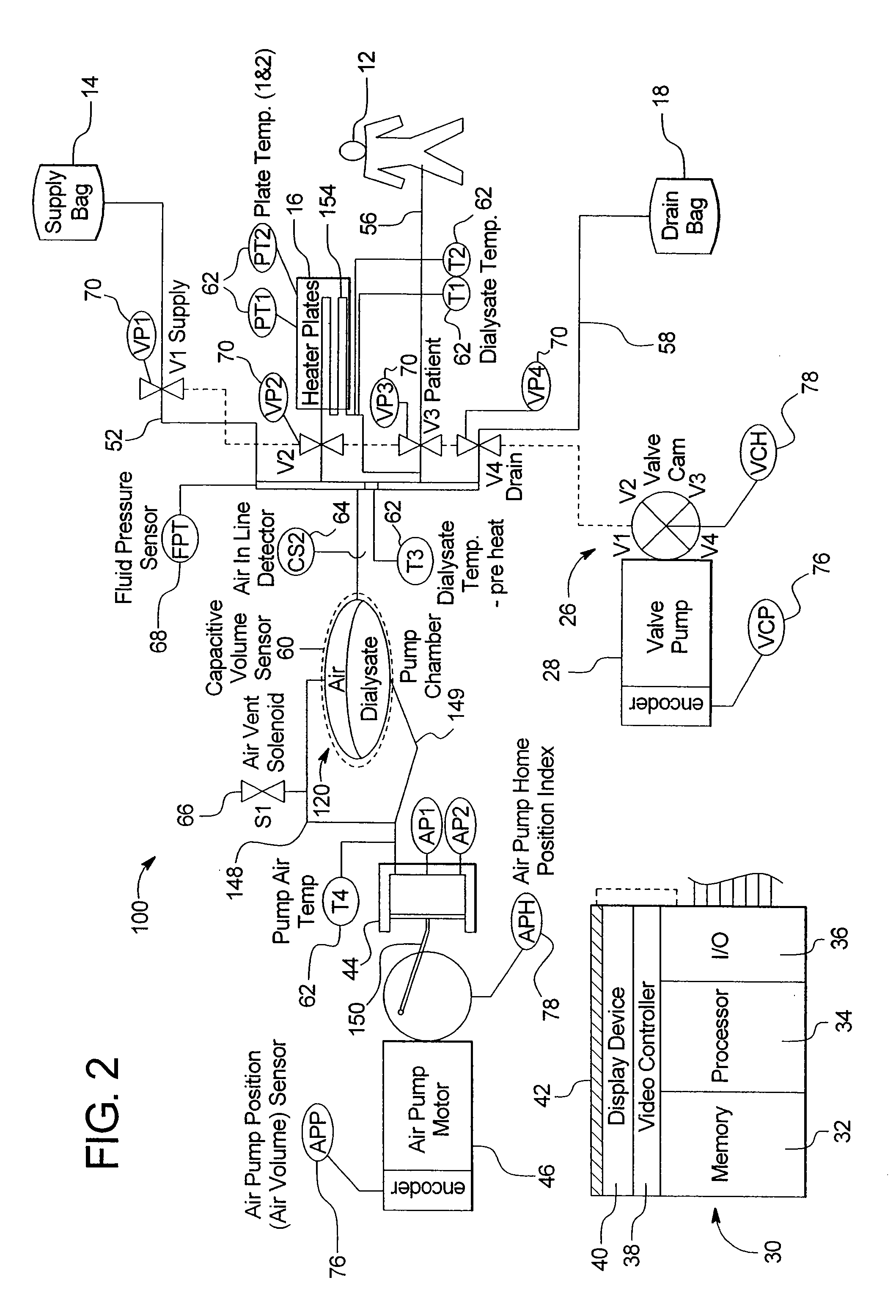
[0081] Referring now to the drawings and in particular to FIG. 1, a typical therapy performed by the sys...


PUM


Abstract

A method for making a peritoneal dialysis therapy machine having a tubing set includes: packaging an end of each of a plurality of the tubes of the set in a body; arranging the tubes according to a sequence of steps of a dialysis treatment set-up so that a user is urged to remove the tubes from the single body in a desired order; and configuring the body to plug connectors attached to each of the ends of the tubes.

Description

PRIORITY CLAIM [0001] This application claims priority to and the benefit as a continuation application of U.S. patent application “Disposable Medical Fluid Unit Having Rigid Frame,” Ser. No. 10 / 155,384 filed May 24, 2002.BACKGROUND OF THE INVENTION [0002] The present disclosure generally relates to dialysis systems. More specifically, the present disclosure relates to automated peritoneal dialysis systems. The present disclosure also relates to methods of performing automated peritoneal dialysis and devices for performing same. [0003] Due to disease, insult or other causes, a person's renal system can fail. In renal failure of any cause, there are several physiological derangements. The balance of water, minerals and the excretion of daily metabolic load is no longer possible in renal failure. During renal failure, toxic end products of nitrogen metabolism (urea, creatinine, uric acid, and others) can accumulate in blood and tissues. [0004] Kidney failure and reduced kidney functio...

Claims


Application Information

Patent Timeline
Patent Type & Authority Applications(United States)
IPC IPC(8): A61M1/28A61M1/16
CPCA61M1/28A61M2205/127A61M2205/50A61M2205/502A61M1/288A61M2205/581A61M2205/583A61M1/1664A61M1/282A61M2205/505A61M1/155A61M1/1565A61M1/159A61M1/152A61M1/153A61M1/1561A61M5/14593A61M5/145A61M5/14224A61M2205/123A61M2205/125A61M2205/12A61M2205/128A61M2205/126A61M2205/121A61M2205/122
Inventor LUNDTVEIT, LOREN M.ALVARO, JOSEBOWMAN, JOSEPH H. JR.O'SULLIVAN, DANTHOMPSON, STAN
Owner BAXTER HEALTHCARE SA
Why Eureka
Try Eureka