Combustion engine

a combustion engine and combustion chamber technology, applied in the direction of engines, output power, fuel air intakes, etc., can solve the problems of poor volumetric efficiency, negative pressure difference, and risk of premature ignition of the same, and achieve the effect of improving the performance of the internal combustion engin

Inactive Publication Date: 2002-10-08
SAAB AUTOMOBILE AB
View PDF8 Cites 75 Cited by
  • Summary
  • Abstract
  • Description
  • Claims
  • Application Information

AI Technical Summary

Benefits of technology

It is an object of the invention to provide an improved internal combustion engine. Still another object is to achieve better performance of the internal combustion engine at high load.

Problems solved by technology

The problems are aggravated by the fact that the proportion of residual gases in the cylinder is high, with attendant heating of the new charge and risk of premature ignition of the same.
At full throttle, a poor volumetric efficiency is obtained as a result of a negative pressure difference between inlets and outlets during the period when inlet valves and outlet valves are open simultaneously.
At low engine speed, this negative pressure difference is caused by a disruptive pressure pulse in the exhaust branch pipe from the next cylinder igniting.
At high engine speed, throttling of the engine at the exhaust-gas turbine also contributes to creating a negative pressure difference.
As the load increases, pressure limitations are required because of knocking, as a result of which the charging pressure must be limited at higher loads.
This has a negative effect on the performance of the engine.

Method used


Image

  • Combustion engine
  • Combustion engine
  • Combustion engine

Examples


Embodiment Construction

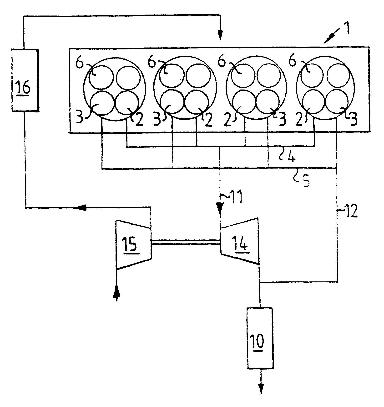
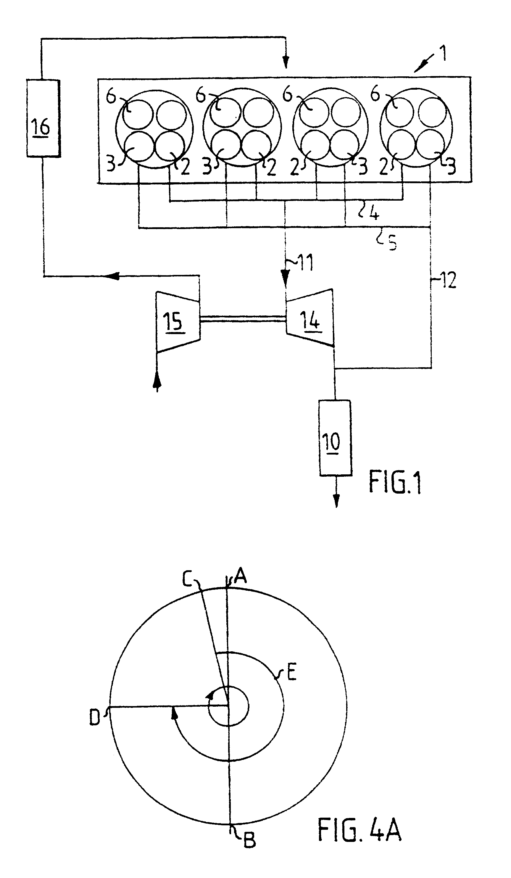
FIG. 1 shows diagrammatically a multi-cylinder internal combustion engine 1 according to the invention made as an Otto engine. The cylinders of the engine each have at least two exhaust-gas valves 2 and 3. From the first exhaust-gas valves 2 of the cylinders, exhaust gas is conducted out to a first exhaust manifold 4 common to the cylinders. From the second exhaust-gas valves 3 of the cylinders, exhaust gas is conducted out to a second exhaust manifold 5 common to the cylinders. The first exhaust manifold 4 is connected to a catalyst 10 via a first exhaust pipe 11, and the second exhaust manifold 5 is connected to the catalyst 10 via a second exhaust pipe 12. One or more silencers (not shown) is or are present in the conventional manner downstream of the catalyst 10.

The engine 1 is also equipped for supercharging by means of a compressor driven via an exhaust-driven turbine. The exhaust-gas turbine 14 is connected in the first exhaust pipe 11 and is consequently fed from the first e...


PUM


Abstract

A turbo-fed internal combustion engine has a first and a second exhaust-gas valve per cylinder, these exhaust-gas valves each being connected to their respective exhaust manifold. One exhaust manifold conducts exhaust gases to an exhaust-gas turbine and the other exhaust manifold conducts subsequent exhaust gases past this exhaust-gas turbine which drives a compressor for charge air. The intake valve of the cylinder is arranged so as, as the engine speed increases, to close either earlier, before the piston reaches its bottom dead center, or later, after the piston has passed its bottom dead center. In this way, the temperature increase resulting from compression in the cylinder is reduced. Cooled air from the compressor can be taken in so as to obtain an adequate degree of filling in the cylinder, with a lower final temperature.

Description

The invention relates to an internal combustion engine provided with a system for controllably opening and closing exhaust and intake valves to the cylinders.STATE OF THE ARTWithin the area of vehicle technology, it is becoming increasingly common to use turbocharged engines, that is to say engines in which supercharging is effected by means of a compressor which is driven by an exhaust-driven turbine. At high power, greater charging is used than in an ordinary engine. In order, in this connection, to avoid knocking and excessively high combustion pressures, ignition is set relatively late. This in turn results in the expansion possibility for the combusted gases being small, at the same time as the temperature reduction during expansion does not have time to become as great. The exhaust-gas temperature is therefore high. The problems are aggravated by the fact that the proportion of residual gases in the cylinder is high, with attendant heating of the new charge and risk of prematu...

Claims


Application Information

Patent Timeline
Patent Type & Authority Patents(United States)
IPC IPC(8): F01L1/26F02D13/02F02B37/18F02B37/00F01L1/34F02F1/42F02M35/10
CPCF01L1/26F01L1/34F02B37/00F02B37/02F02B37/18F02D13/0215F02D13/0249F02D13/0257F02D13/0269F02F1/4214F02D13/0261Y02T10/144Y02T10/142Y02T10/12
Inventor OLOFSSON, ERIC
Owner SAAB AUTOMOBILE AB
Why Eureka
Try Eureka