
Fluid meter, in particular water meter with volumetric measurement chamber

Inactive Publication Date: 2005-08-09
ACTARIS SAS
View PDF6 Cites 9 Cited by
  • Summary
  • Abstract
  • Description
  • Claims
  • Application Information

AI Technical Summary

Benefits of technology

[0018]Thanks to the invention, assembly becomes compatible with the quality and productivity constraints of mass production assembly, with no operations additional to insertion of the

Problems solved by technology

These relatively high forces may expel the seal from the groove, detaching the seal from the measurement chamber, with the risk of deforming the seal in a direction opposite to the insertion direction, and even cutting the seal, the measurement chamber being assembled to the tank with no seal, making the meter useless.
These problems are incompatible with mass production assembly of the meter.

Method used


Image

  • Fluid meter, in particular water meter with volumetric measurement chamber
  • Fluid meter, in particular water meter with volumetric measurement chamber
  • Fluid meter, in particular water meter with volumetric measurement chamber

Examples


Embodiment Construction

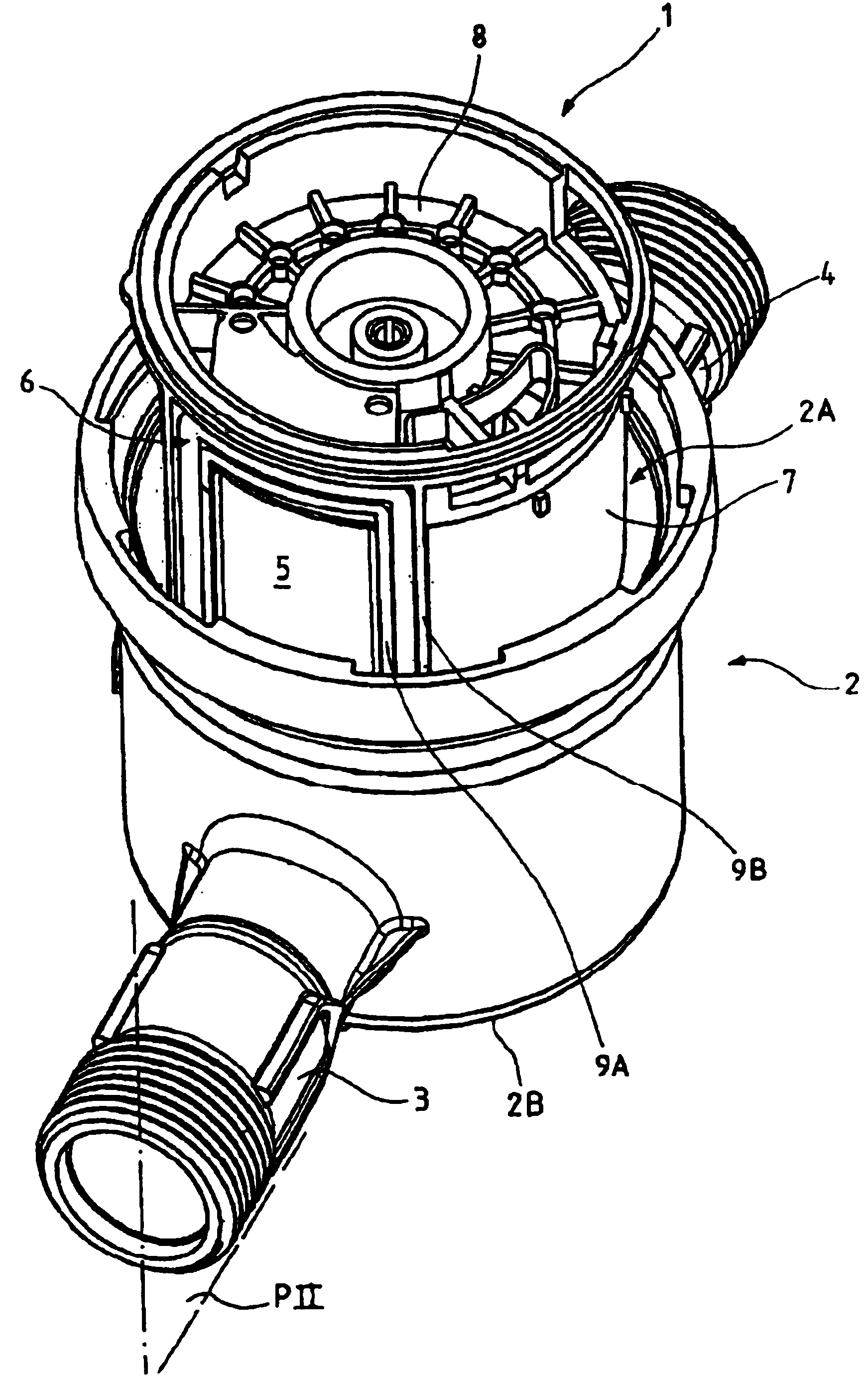
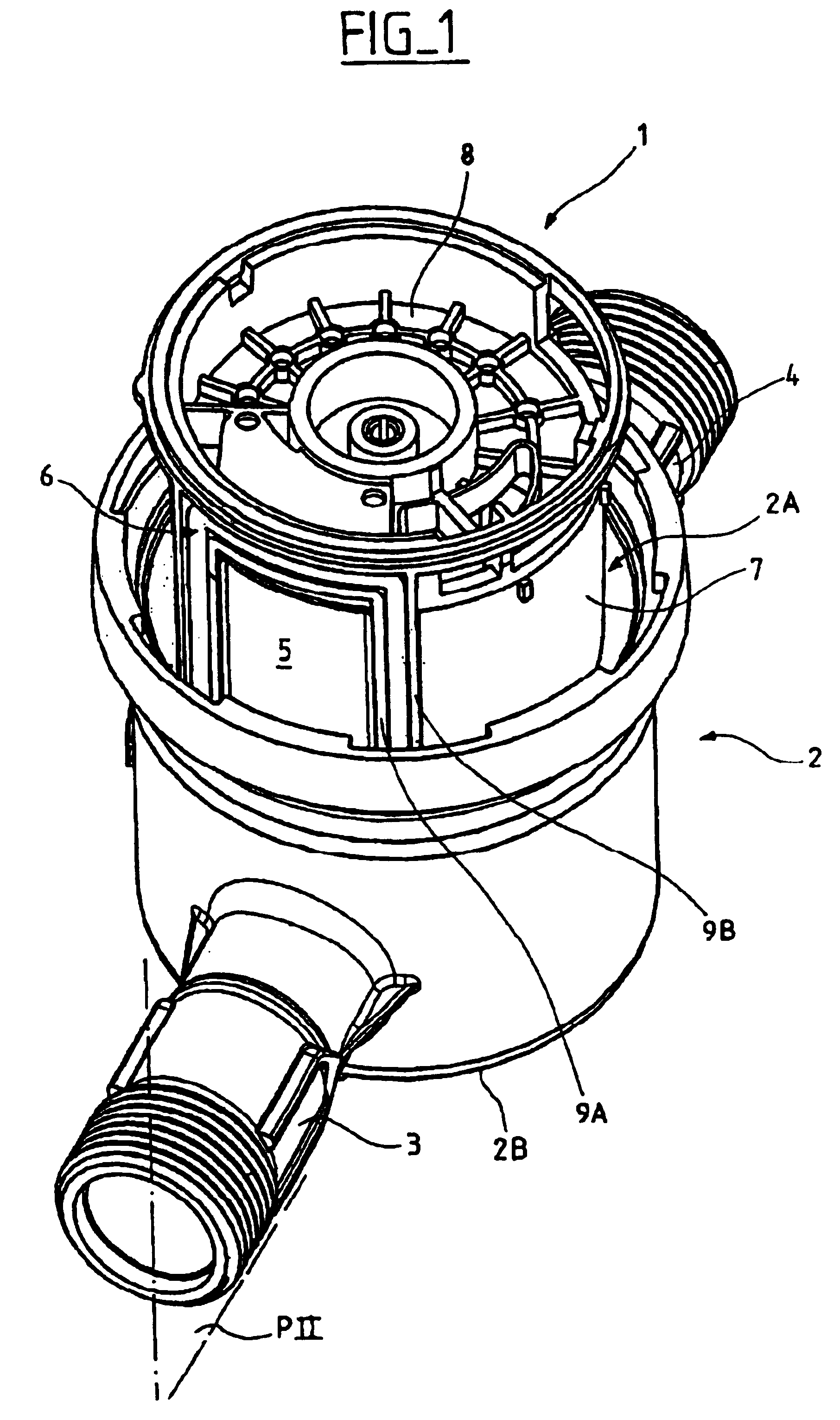
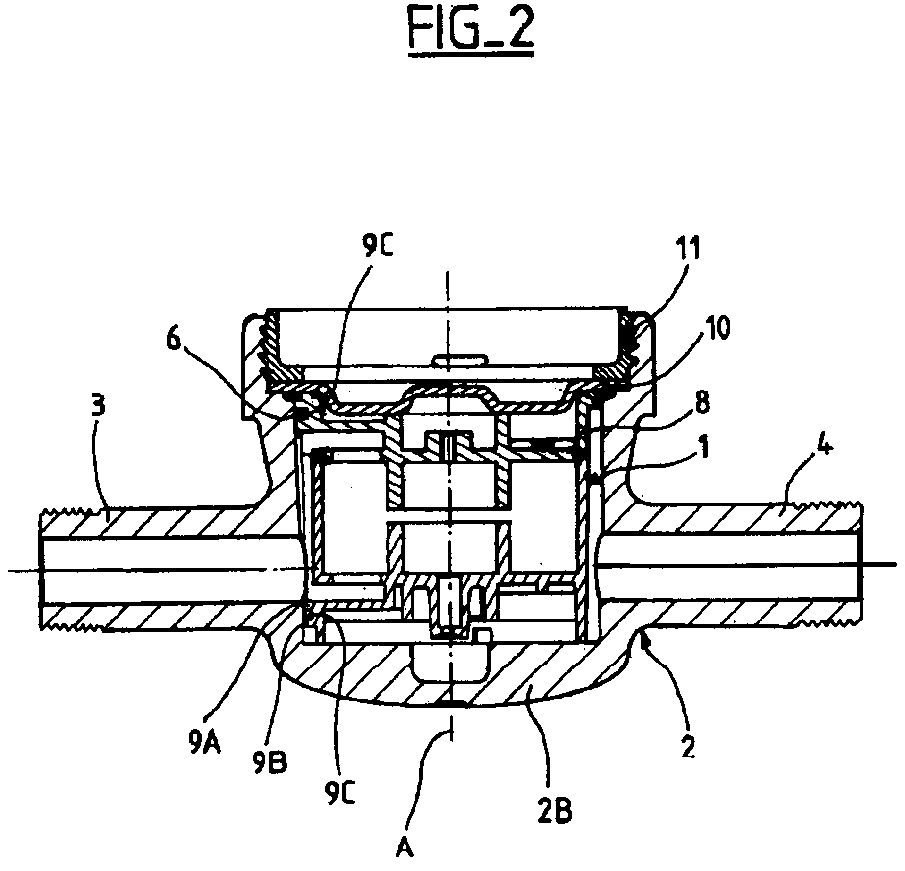
[0022]As shown in FIG. 1, a fluid meter, here a water meter, includes an oscillating piston type volumetric measurement chamber 1 inserted in an insertion direction into a tank 2 having an inlet pipe 4 and an outlet pipe 3. To be more precise, the chamber is inserted via an opening 2A opposite the bottom 2B of the tank. The insertion direction is parallel to the axis A of symmetry of the tank 2.

[0023]The external enclosure 7 and the lid 8 of the measurement chamber form an orifice 5 on the lateral wall of the chamber 1 that extends over a particular height and is adapted to be connected in sealed manner to the outlet pipe 3; to this end, a circular section seal 6 that is radially elastic and of generally rectangular shape, like the orifice, is fitted into a groove formed on the external face of the enclosure 7 of the chamber around the orifice 5.

[0024]The groove is formed by two ribs 9A, 9B molded onto the exterior enclosure 7 and the lid 8 of the measurement chamber around the orif...


PUM


Abstract

A fluid meter, in particular a water meter, comprises a tank having a bottom and into which is inserted through an opening opposite the bottom in an insertion direction parallel to its axis of symmetry a measurement chamber having at least one lateral orifice connected in a sealed manner to a pipe of the tank via a seal that is compressed between an external surface of the chamber, called the first surface, and an internal surface of the tank, called the second surface. The first and second surfaces are inclined to the axis of symmetry of the tank and the minimum distance between the first and second surfaces and the axis of symmetry is near the bottom of the tank.

Description

RELATED APPLICATION:[0001]This application is related to and claims the benefit of priority from French Patent Application No. 03 50087, filed on Apr. 4 2003, the entirety of which is incorporated herein by reference.BACKGROUND OF THE INVENTION[0002]1. Field of the Invention[0003]The present invention relates to a fluid meter, in particular a water meter with a volumetric measurement chamber.[0004]2. Description of the Prior Art[0005]A prior art meter of this kind comprises a casing or tank having an inlet pipe and an outlet pipe and into which is inserted an oscillating piston type volumetric measurement chamber. The measurement chamber has at least one inlet orifice and at least one outlet orifice. This kind of meter is well known to the person skilled in the art.[0006]In some forms of measurement chamber, like that shown in FIG. 1, the inlet orifice or the outlet orifice 5 extends over a particular height on the lateral wall of the enclosure of the chamber 1. This orifice must be...

Claims


Application Information

Patent Timeline
IPC IPC(8): G01F3/08G01F3/02
CPCG01F3/08
Inventor MERCIER, ALCIDE
Owner ACTARIS SAS
Learn More