Vehicular mirror assembly incorporating multifunctional illumination source

a technology of multifunctional illumination source and mirror assembly, which is applied in the direction of furniture parts, lighting and heating equipment, lighting support devices, etc., can solve the problems of exacerbated undesirable location of available interior volume, difficult to incorporate multiple illumination modes in a single external mirror, and little interior volume in the mirror assembly

Inactive Publication Date: 2005-08-09
MAGNA MIRRORS OF AMERICA INC
View PDF140 Cites 74 Cited by
  • Summary
  • Abstract
  • Description
  • Claims
  • Application Information

AI Technical Summary

Problems solved by technology

Unfortunately, several characteristics of the external mirror and the vehicle marketplace make it difficult to incorporate multiple illumination modes in a single external mirror.
The tendency to reduce or minimize the cross-sectional profile of the mirror results in little available interior volume in the mirror assembly for locating the light assemblies needed for the multiple illumination modes.
The undesirable location of available interior volume is exacerbated when multiple modes of illumination are desired.
The characteristics of the vehicle parts manufacturing marketplace in general and the exterior mirrors specifically impose additional constraints and hurdles for providing a suitable multiple illumination mode external mirror.
Illumination devices in vehicles have typically employed incandescent lamps, which typically have a limited useful life, lack ease of replacement, and have a tendency to burn out, particularly in a harsh environment.
Furthermore, incandescent lamps tend to be relatively large.
However, there are limitations in doing so.
Significantly, it is difficult to emit white light from an LED, and, although it is possible to do so, the white-light LEDs can be expensive.

Method used


Image

  • Vehicular mirror assembly incorporating multifunctional illumination source
  • Vehicular mirror assembly incorporating multifunctional illumination source
  • Vehicular mirror assembly incorporating multifunctional illumination source

Examples


first embodiment

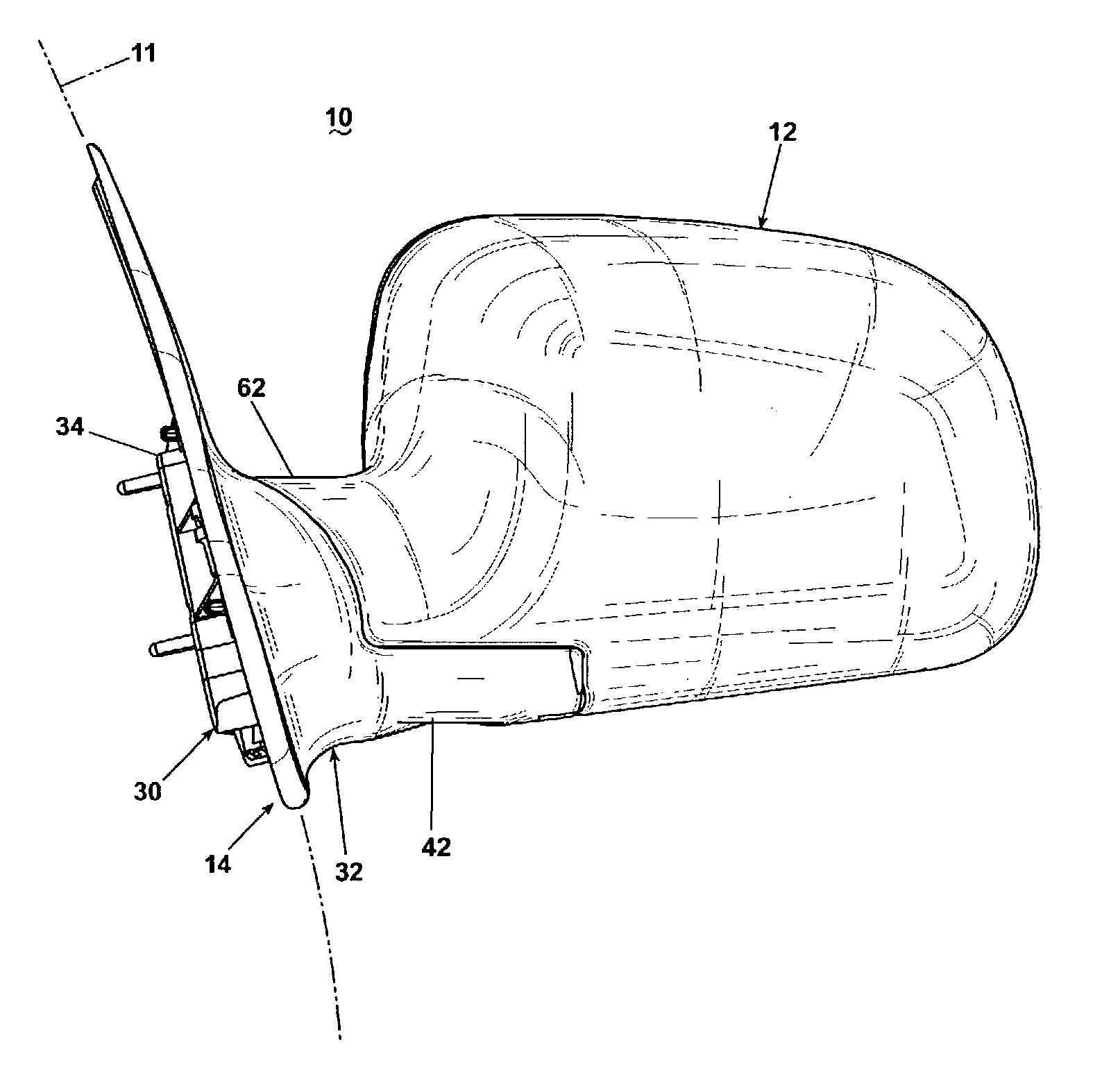
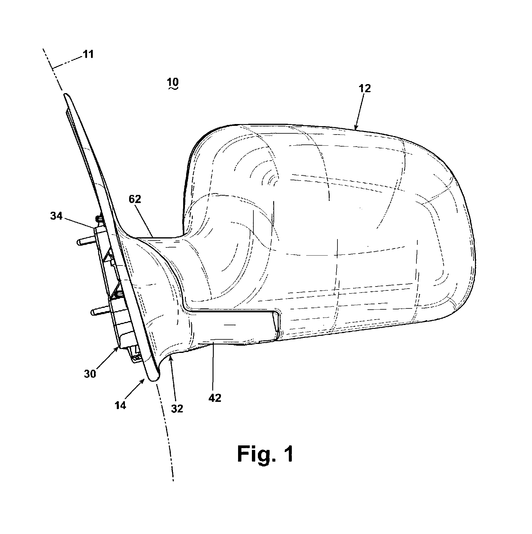
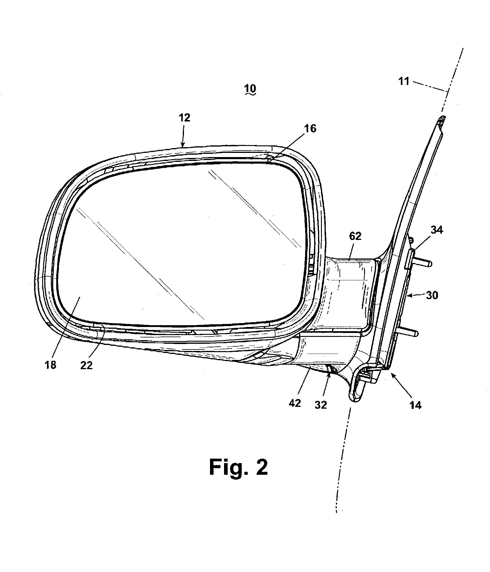
[0051]FIGS. 1–4 illustrate a vehicular mirror system comprising an external mirror assembly 10 of the type suitable for mounting to the exterior of a motor vehicle 11. The external mirror assembly 10 comprises a breakaway moveable portion 12 pivotally mounted to fixed support portion 14, which is adapted to be mounted to the vehicle 11. The moveable portion 12 is closed on a forward side and defines a recess 16 on its rear side in which is received a mirror 18.

[0052]Referring to FIG. 5 specifically, and FIGS. 1–4 generally, the mirror recess 16 of the moveable portion 12 is preferably sized to receive a mirror positioning mechanism comprising a mirror reflective element 22, preferably an electrochromic mirror reflective element, mounted to a drive unit 24, which is sometimes referred to as a mirror actuator, or a “power pack.” The drive unit 24 mounts to the interior of the moveable portion 12 in a well-known manner to provide for adjusting the tilt of the reflective element 22 abou...

second embodiment

[0090]FIGS. 12–15 illustrate an external mirror assembly 210 of the type suitable for mounting to the exterior of the motor vehicle 11. FIGS. 12 and 13 illustrate the external mirror assembly 210 in an extended position for use when the vehicle 11 is being driven, whereas FIGS. 14 and 15 illustrate the exterior mirror assembly 210 in a folded position for use when the vehicle 11 is parked.

[0091]The external mirror assembly 210 comprises a moveable portion 212 pivotally mounted to a fixed support portion 214, which is adapted to be mounted to the vehicle 11. The moveable portion 212 is closed on a forward side and defines a recess 216 on its rear side in which is received a mirror 218.

[0092]Referring also to FIG. 16, the mirror recess 216 of the moveable portion 212 is preferably sized to receive a mirror positioning mechanism comprising a frame 222 (also referred to in the art as a glass housing, case, or carrier) mounted to a drive unit 224, which is sometimes referred to as a “pow...

third embodiment

[0118]The illuminating assembly 330 for the third embodiment comprises a dish reflector 332, which mounts the light element 284. A post 334 extends upwardly from a rear portion of the dish reflector 332 and through an opening in the lip 254 of the support base 244. A spur gear 336 is mounted to the upper end of the post 334 to thereby secure the dish reflector 332 to the lip 254.

[0119]The collar 238 of the support bracket 228 comprises an external gear 338 instead of the cam 240 found in the first embodiment. The external gear 338 meshes with the spur gear 336. When the moveable portion 212 is rotated between the extended and folded positions by the pivot mechanism 234, the external gear 338 rotates the spur gear 336 to rotate the dish reflector 332 from the rearward position as seen in FIG. 23 to the forward position as seen in FIG. 24.

[0120]FIGS. 25 and 26 illustrate a fourth embodiment of the external mirror assembly according to the invention. The fourth embodiment mirror assemb...


PUM


Abstract

The invention relates to an external rearview mirror having an illumination source capable of illuminating various portions of an vehicle and the surrounding area depending upon the operational status of the vehicle. The illumination source is adjustable to selectively illuminate predetermined areas of the vehicle and the surrounding area. Two sets of light-emitting diodes of selected colors can be arranged and controlled so that the first set of LEDs can be selectively illuminated as a turn signal indicator, and the first set and second set can be selectively illuminated so that the combined illumination forms a white light suitable for illumination, such as a “puddle light” or backup light.

Description

CROSS REFERENCE TO RELATED APPLICATIONS[0001]This application claims the benefit of U.S. provisional application Ser. No. 60 / 319,174, filed Apr. 9, 2002; 60 / 319,175, filed Apr. 9, 2002; and 60 / 319,323, filed Jun. 18, 2002, which are incorporated herein in their entirety.BACKGROUND OF INVENTION[0002]1. Field of the Invention[0003]The invention relates to an external vehicle mirror and, more particularly, to an external vehicle mirror having multiple illumination modes. In one aspect, the invention relates to vehicle external mirrors incorporating an illumination device mounted for movement between multiple functional positions. In another aspect, the invention relates to an assembly of light-emitting diodes of different colors for selectively producing, in combination, colored light for different vehicular functions.[0004]2. Description of the Related Art[0005]External mirrors are ubiquitous for contemporary motor vehicles and have long been used to aid the driver in operating the ve...

Claims


Application Information

Patent Timeline
Patent Type & Authority Patents(United States)
IPC IPC(8): B60Q1/26B60Q1/32B60R1/12
CPCB60Q1/2665B60Q1/323B60R1/1207B60Q2400/20B60Q2400/40B60Q1/247
Inventor FOOTE, KEITH D.BODDY, IANBROWN, KRIS D.PETERSON, KENNETH C.
Owner MAGNA MIRRORS OF AMERICA INC
Why Eureka
Try Eureka