Lacrosse stick head

a technology of lacrosse stick and head, which is applied in the field of lacrosse stick, can solve the problems of not addressing the maintenance concern, reducing the effective catching area of the lacrosse stick, so as to prevent the wear of the stringing, improve the ball retention effect, and reduce the pocket area

Inactive Publication Date: 2005-08-09
WARRIOR SPORTS INC
View PDF10 Cites 27 Cited by
  • Summary
  • Abstract
  • Description
  • Claims
  • Application Information

AI Technical Summary

Benefits of technology

[0010]It is a further object of the present invention to provide a lacrosse head that prevents wear of the stringing when the ball resides in the lacrosse head.
[0011]It is another object of the present invention to provide a lacrosse head that provides a decreased pocket area for better ball retention without decreasing the size of the catching area.
[0012]It is still another object of the present invention to provide a lacrosse head that assists in preventing the lacrosse ball from being dislodged from the head during use.
[0013]It is still a further object of the present invention to provide a lacrosse head with a throat configuration that is stronger and lighter than prior lacrosse heads.

Problems solved by technology

While these head configurations, which vary from the traditional configuration, provide different characteristics with regard to playability and feel, they do not address the concern of maintaining a lacrosse ball in the head once received in the netting.
Attempts have been made in this regard to provide structure for a lacrosse head that helps maintain a lacrosse ball in the pocket and help to resist it from being checked from the lacrosse head, but these structures have caused other problems.
However, the extensions of these ridges from the sidewalls into the pocket also decreases the effective catching area of the lacrosse head.
This configuration does provide some ball retention attributes, but it decreases the catching area of the head.
None of these prior lacrosse heads, however, provide any structure to narrow the pocket of the head and thereby keep the lacrosse ball, while in the head, in line with the center of the stick without narrowing the effective catching area of the head.

Method used


Image

  • Lacrosse stick head
  • Lacrosse stick head
  • Lacrosse stick head

Examples


Embodiment Construction

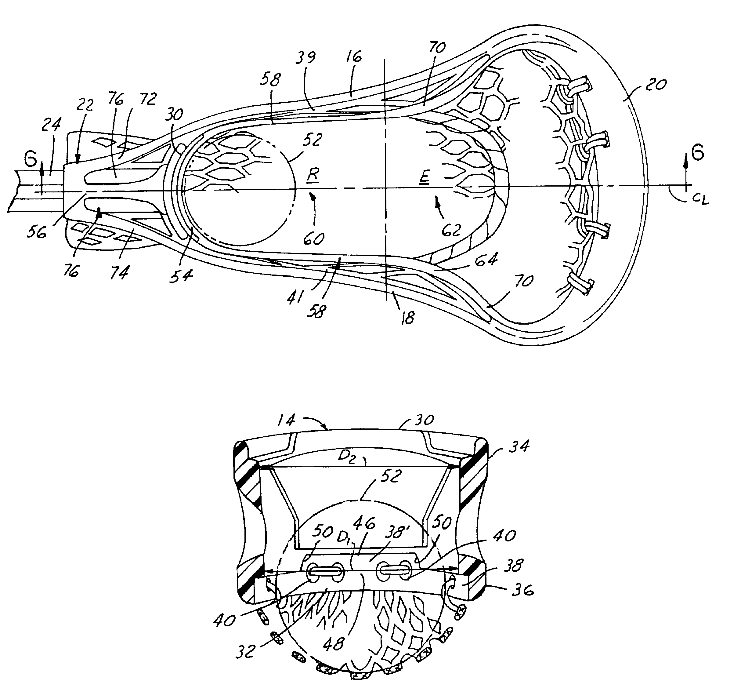
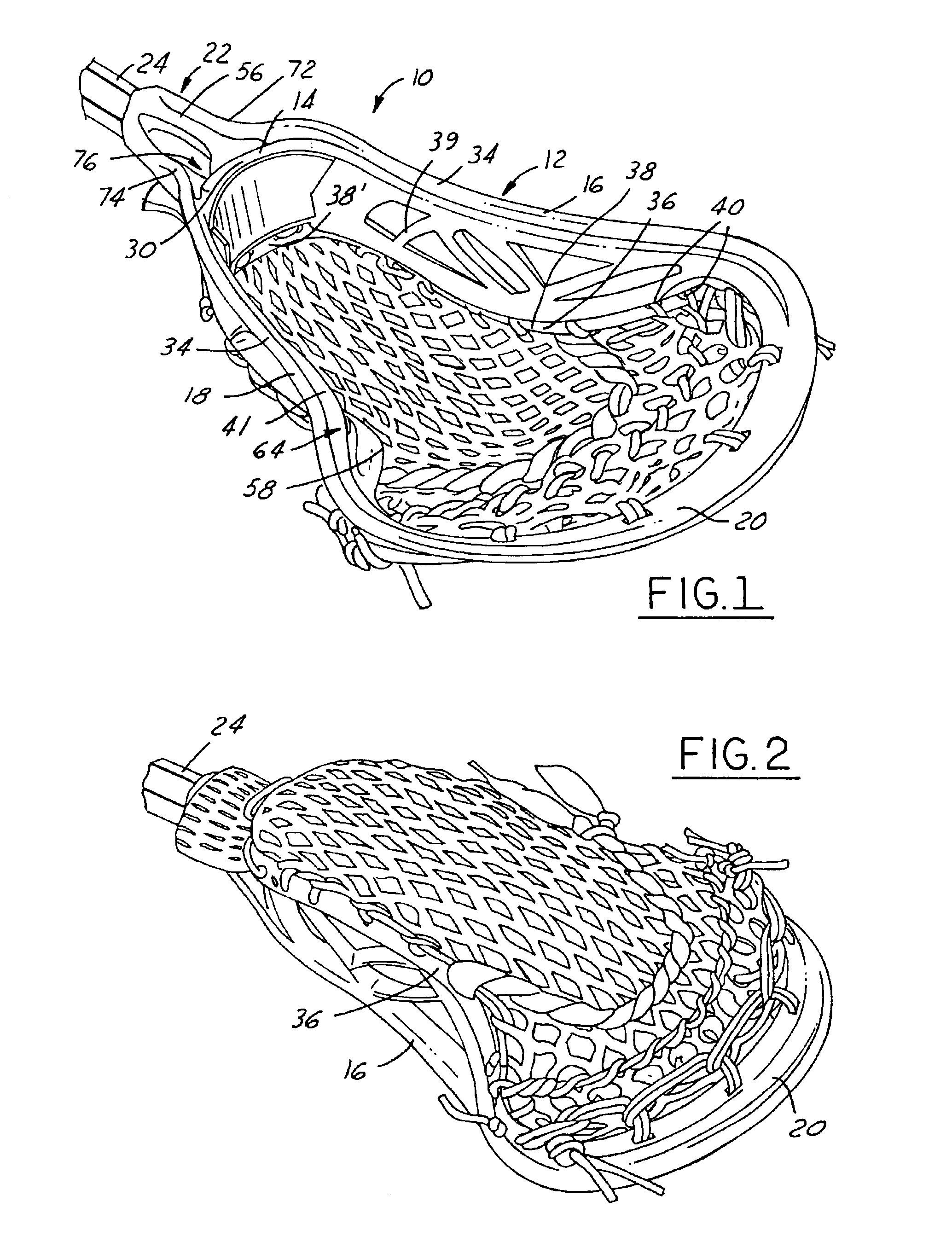
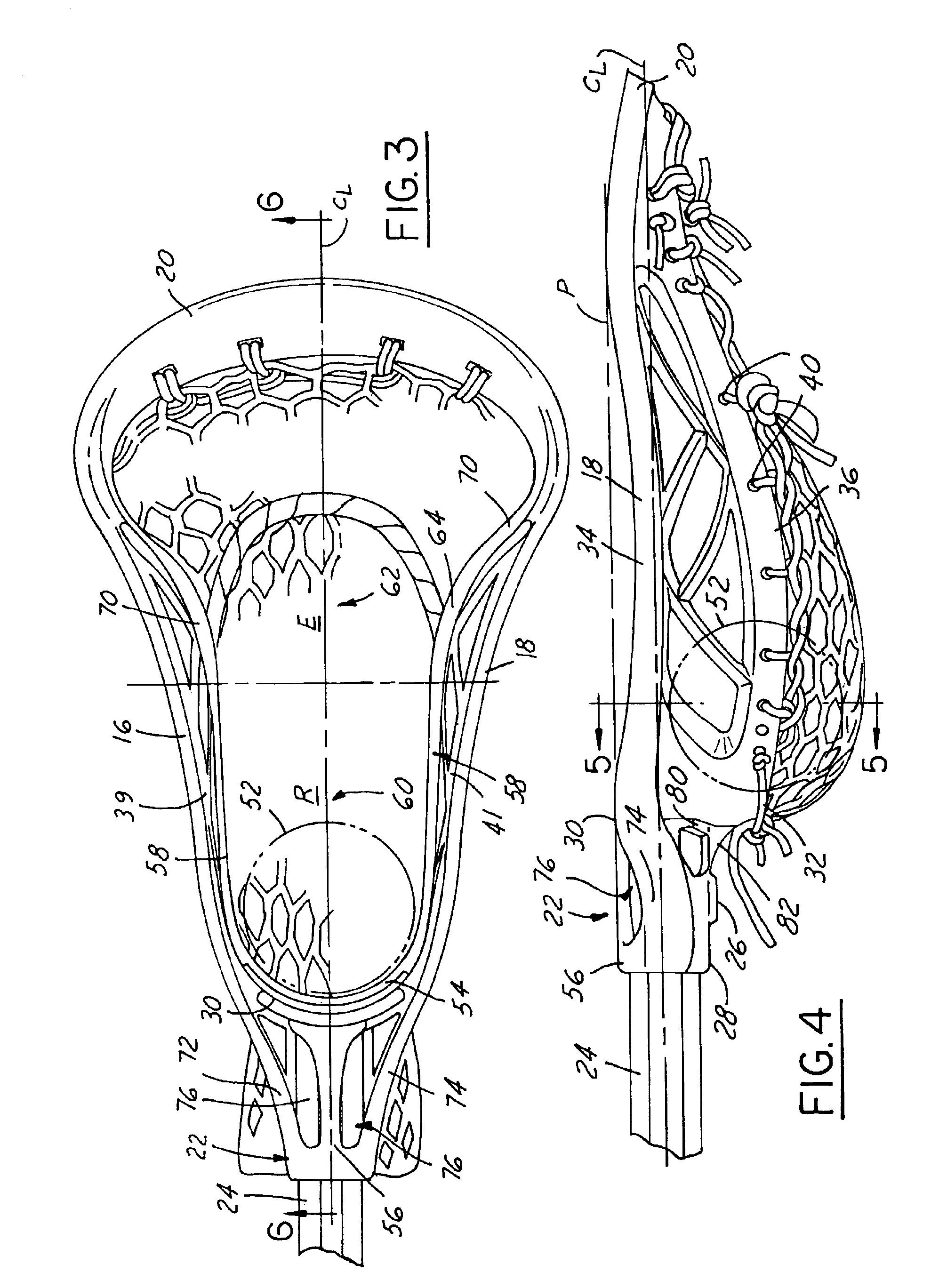
[0023]Referring now to FIGS. 1 and 2, which illustrate a lacrosse head 10 in accordance with the present invention. The lacrosse head 10 has a frame element 12, which includes a base or arcuate wall 14, a pair of opposing sidewalls 16, 18, and a scoop or lip 20 connecting the pair of opposing sidewalls 16, 18 opposite the base 14. The lacrosse head 10 has a throat or socket 22 that extends generally rearwardly from the frame element 12 for attachment of a stick handle or element 24 therein. The stick handle 24 is preferably secured in the socket 22 by a securing means, such as a screw or the like, which is inserted into a fixation hole 26 formed in the socket 22. The fixation hole 26 is preferably formed in a lower surface 28 of the socket 22 (FIG. 4). However, it should be understood that the fixation hole 26 can be formed in any portion of the socket 22.

[0024]The base 14 has an upper rim 30 and a lower rim 32. Additionally, the sidewalls 16, 18 each have an upper rim 34 and a lowe...


PUM


Abstract

A lacrosse head for use with a lacrosse handle includes a frame element including an arcuate wall, a scoop opposing the arcuate wall, and a pair of opposing sidewalls. The sidewalls generally extend between the arcuate wall and the scoop. The frame element has a socket extending rearwardly therefrom for receipt of a handle therein. The lacrosse head has a plurality of net attachment means formed therein for attachment of lacrosse net thereto. The lacrosse head has a pocket area defined by a lower portion of the arcuate wall, the scoop, and a lower portion of each of the pair of opposing sidewalls. The lacrosse head also has a catching area defined by an upper portion of the arcuate wall, the scoop, and an upper portion of each of the pair of opposing sidewalls. The catching area of the head is larger than the pocket area.

Description

CROSS REFERENCE TO RELATED APPLICATIONS[0001]This is a continuation of U.S. patent application Ser. No. 09 / 862,012, filed on May 21, 2001, which is now U.S. Pat. No. 6,561,932.TECHNICAL FIELD[0002]The present invention relates generally to a lacrosse head and, more particularly, to a lacrosse head for a lacrosse stick that can more accurately locate a lacrosse ball in the pocket of the head and therefore provide improved ball control, retention, and playability.BACKGROUND OF THE INVENTION[0003]Current lacrosse heads are typically constructed of an open frame having a base with a concave interior surface that defines a ball rest, a pair of sidewalls that diverge from the base, and a lip or scoop that interconnects the sidewalls remotely of the base. Openings or other attachment structures are carried by the frame for securing a lacrosse net around the back side of the frame, leaving the opposing front side of the frame open for receiving lacrosse balls. A throat or other structure ex...

Claims


Application Information

Patent Timeline
Patent Type & Authority Patents(United States)
IPC IPC(8): A63B59/02A63B59/00
CPCA63B59/02A63B59/025A63B2243/005A63B59/20A63B59/30A63B2102/14A63B49/025
Inventor MORROW, DAVIDHUBBARD, JESSE
Owner WARRIOR SPORTS INC
Why Eureka
Try Eureka