Medical robot for myopic surgery

A medical robot and myopia surgery technology, applied in the medical field, can solve problems such as single control direction, unfavorable assembly structure, and material fatigue, and achieve the effects of low production cost, convenient operation, and precise work

Active Publication Date: 2019-01-11
上海西地众创空间管理有限公司
View PDF11 Cites 3 Cited by
  • Summary
  • Abstract
  • Description
  • Claims
  • Application Information

AI Technical Summary

Problems solved by technology

[0006] The purpose of the present invention is to provide a medical robot for myopia surgery, which solves the problem that the control direction of the snake robot in the prior art is single and can only be preset, the internal stress of the elastic parts is not conducive to assembly, and the structure itself will produce stress changes or even appear. Material fatigue and other issues

Method used


Image

  • Medical robot for myopic surgery
  • Medical robot for myopic surgery
  • Medical robot for myopic surgery

Examples


Embodiment 1

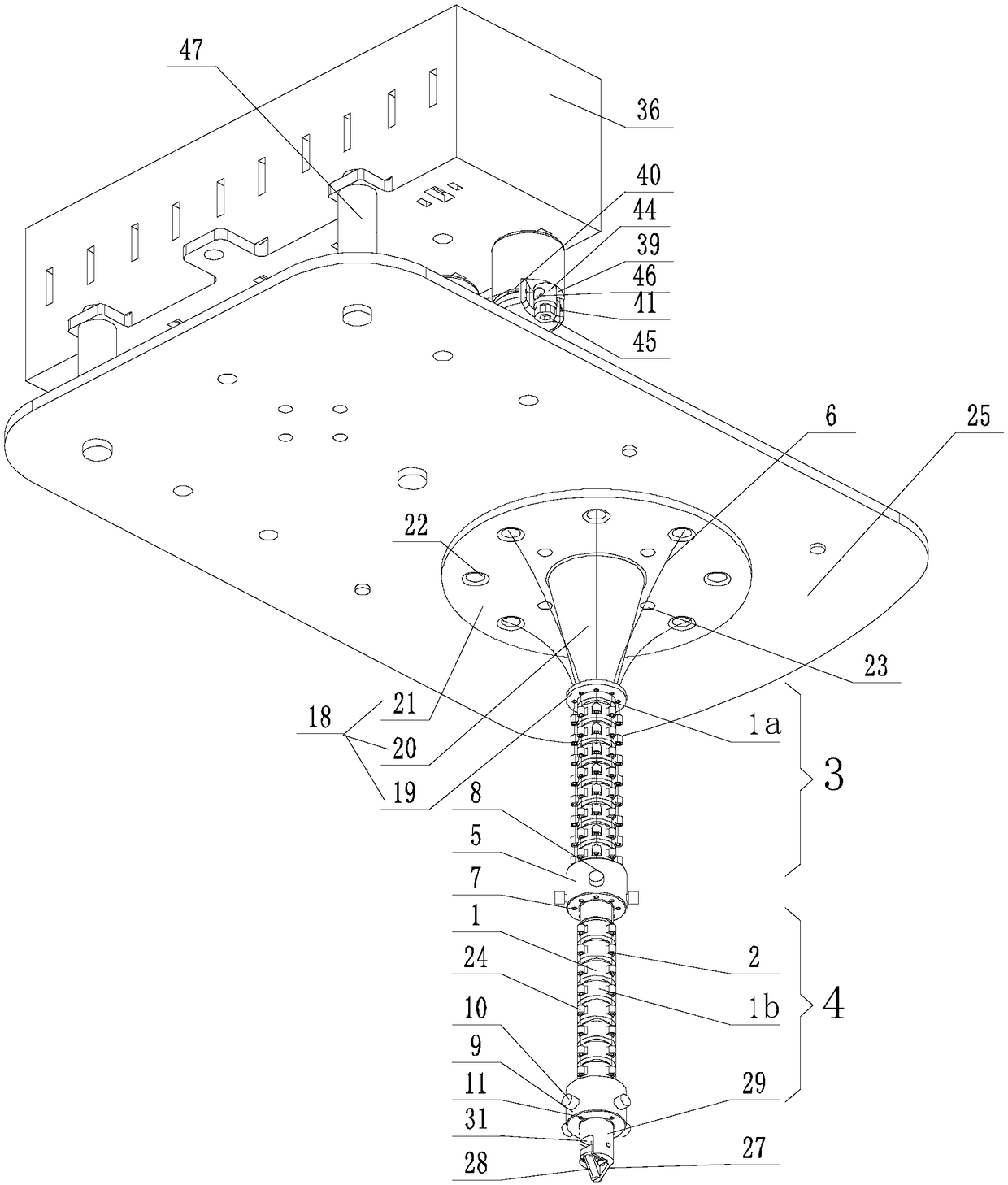
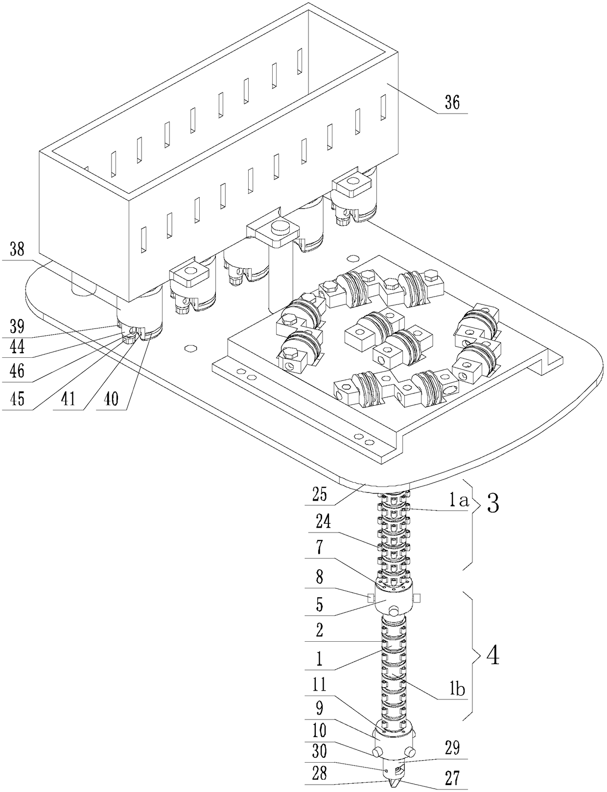
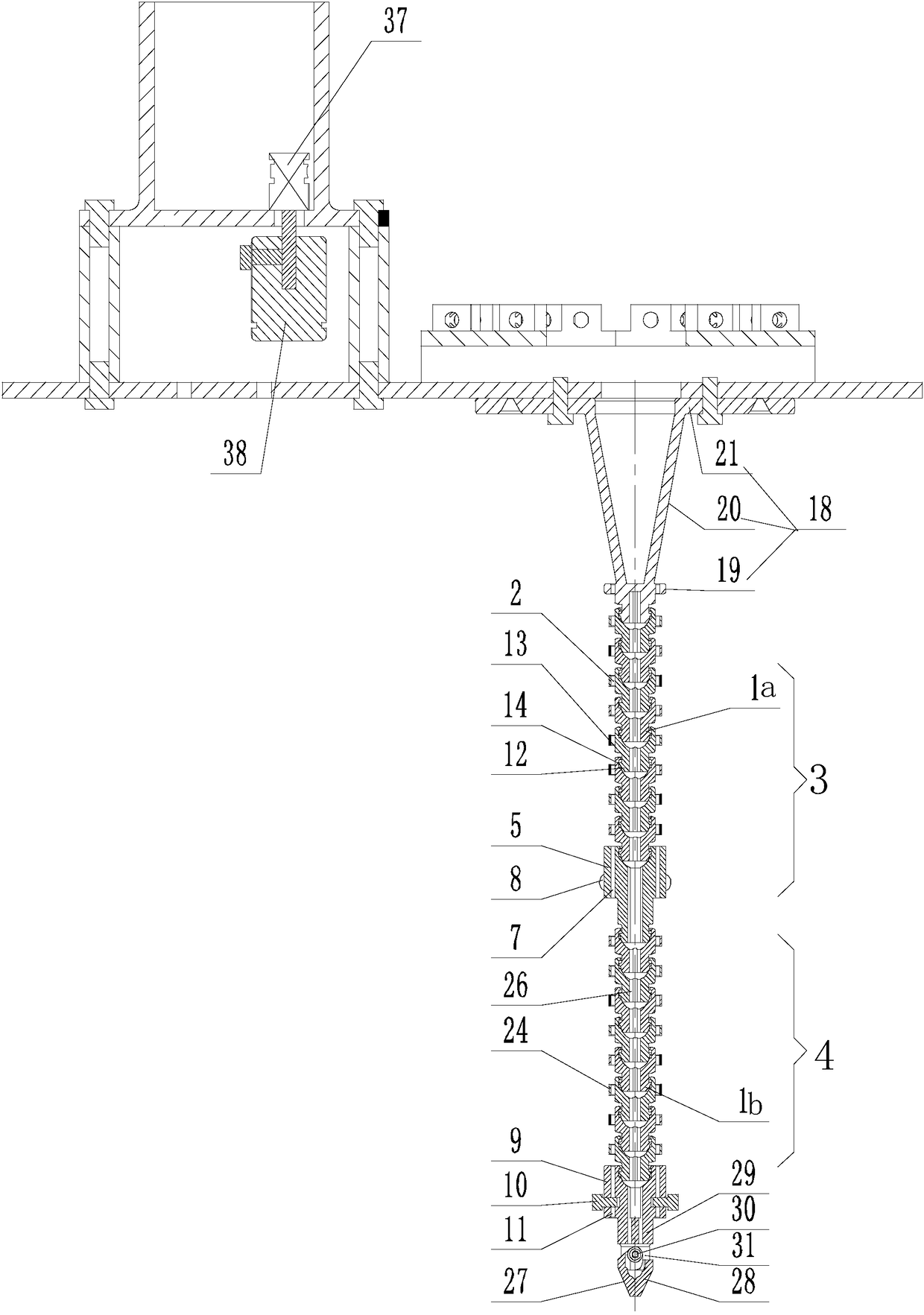
[0063] Such as Figure 1-Figure 10 As shown, the present invention is used for the medical robot of myopia operation, comprises drive line 6 and the coiling device that connects in sequence, drive device, support plate 25, joint section and clamping assembly, and described joint section comprises several successive ball joints The joint unit 1 is provided with a main through hole 26 and an even number of wire holes 2. The axes of the wire holes 2 are all parallel to the axis of the main through hole 26 and along the center of the axis of the main through hole 26. Symmetrical, and the wire holes 2 of two adjacent joint units 1 correspond one-to-one;

[0064] The joint unit 1 located at the head end of the joint segment is fixed on the support plate 25, the joint unit 1 located at the end of the joint segment is connected to the clamping assembly, the drive device is fixed on the support plate 25, and the output shaft of the motor in the drive device is connected to the line de...

Embodiment 2

[0074] This embodiment is an illustration of the manner in which the driving wire 6 is fixed at the tail end of the joint segment.

[0075] Such as Figure 1-Figure 3 as well as Figure 13-Figure 14 As shown, a wire fixing seat 9 and several limit bolts 10 are arranged at the tail end of the joint segment, and the bottom of the wire fixing seat 9 is spherically hinged with the joint unit 1 at the tail end of the joint segment. There are several through holes II11, the limit bolts 10 are threadedly connected with the wire fixing seat 9, and the rotation of the limit bolts 10 can make the ends of the rods respectively inserted into one of the through holes II11, and the joint drive wires are respectively inserted into One through hole II11, and each is pressed on the hole wall of the through hole II11 by a limit bolt.

Embodiment 3

[0077] This embodiment is to illustrate the actual use of the joint segment.

[0078] Such as Figure 1-Figure 7 As shown, there are two joint segments, which are divided into the first closing stage 3 and the second joint segment 4 located on the side away from the driving end in the first closing stage. The joint unit in the first closing stage 3 is the first joint unit 1a, the joint unit in the second joint segment 4 is the second joint unit 1b, and the number of wire holes 2 on the first joint unit 1a is eight, which is twice the number of wire holes 2 on the second joint unit 1b , a wire solid block 5 is arranged between the first closing stage 3 and the second joint segment 4, and one end of the wire solid block 5 is ball-hinged with the tail end of the first closing stage 3, and the other end of the wire solid block 5 is connected to the second joint segment. The head end of the joint segment 4 is hinged, and the number of joint driving wires is the same as the number ...


PUM


Abstract

The invention discloses a medical robot for myopic surgery, comprising a driving wire, and sequentially connected winding device, driving device, support plate, joint section and clamping assembly. The joint section comprises a plurality of joint units hinged in sequence by balls, and a main through hole and a lead hole are arranged on the joint unit. The head end of the joint segment is fixed onthe support plate, and the end of the joint segment is connected with the clamping assembly; the driving wire is divided into a head driving wire and a joint driving wire. One end of the driving wireis fixed on a winding device, and the other end of the joint driving wire passes through the wire holes in each joint unit in turn and is fixed on the tail end of the joint segment. The invention eliminates the defects in the prior art, and also obtains the advantages of multiple controllable directions, simple assembly, long service cycle and accurate work.

Description

technical field [0001] The invention relates to the medical field, in particular to a medical robot for myopia surgery. Background technique [0002] Medical robots have the advantages of accurate positioning, stable operation, strong dexterity, large working range, and are not afraid of radiation and infection. They can not only assist doctors in the precise positioning of surgical sites, but also achieve minimal surgical damage and improve the accuracy of disease diagnosis and surgical treatment. and quality, improve surgical safety, shorten treatment time, and reduce medical costs. In recent years, its research has become a new field of robot applications, especially multifunctional medical robots have become a new direction for the development of medical robots. [0003] At present, surgical robots generally adopt a master-slave remote control operation mode. The use of surgical robots helps to improve the accuracy of surgeons' operations, solve the trembling, fatigue,...

Claims


Application Information

Patent Timeline
Patent Type & Authority Applications(China)
IPC IPC(8): A61F9/008
CPCA61F9/00804Y02A50/30
Inventor 覃霁沈靖
Owner 上海西地众创空间管理有限公司
Why Eureka
Try Eureka