Surgical table

a surgical table and support surface technology, applied in the field of surgical tables, can solve the problems of increasing fatigue, increasing fatigue, and team members not being able to stand near the patient's body, and achieve the effect of reducing the height of the patient support surfa

Inactive Publication Date: 2005-08-16
RELIANCE MEDICAL PRODS
View PDF32 Cites 46 Cited by
  • Summary
  • Abstract
  • Description
  • Claims
  • Application Information

AI Technical Summary

Benefits of technology

[0009]In one embodiment of the present invention, a surgical table is provided that permits compact lateral tilting of a patient support surface for reducing the height of the patient support surface relative to the floor surface when the surgical table is in a fully lowered condition. In accordance with the principles of the invention, the surgical table includes a patient support surface having a longitudinal axis, a frame attached to the patient support surface, and a base having a support column and a support platform attached to the support column. The surgical table further includes a pair of four-bar linkage mechanisms that allow the frame and the patient support surface to tilt transversely generally about the longitudinal axis and relative to the support platform. Each of the four-bar linkage mechanisms includes a pair of link arms each having one end pivotally attached to the support platform and an opposite end pivotally attached to the frame.

Problems solved by technology

However, such conventional mechanisms are mechanically complex because a set of vertically movable legs must be incorporated into the table design.
Because the patient not conveniently located, surgical team members must stand during surgical procedures, which increases fatigue.
If the support surface is significantly wider that the width of the patient's body, then the surgical team members cannot stand near to the patient's body.
In extreme instances, all portions of the patient's upper torso may not be accessible from a single side of the surgical table.

Method used


Image

  • Surgical table
  • Surgical table
  • Surgical table

Examples


Embodiment Construction

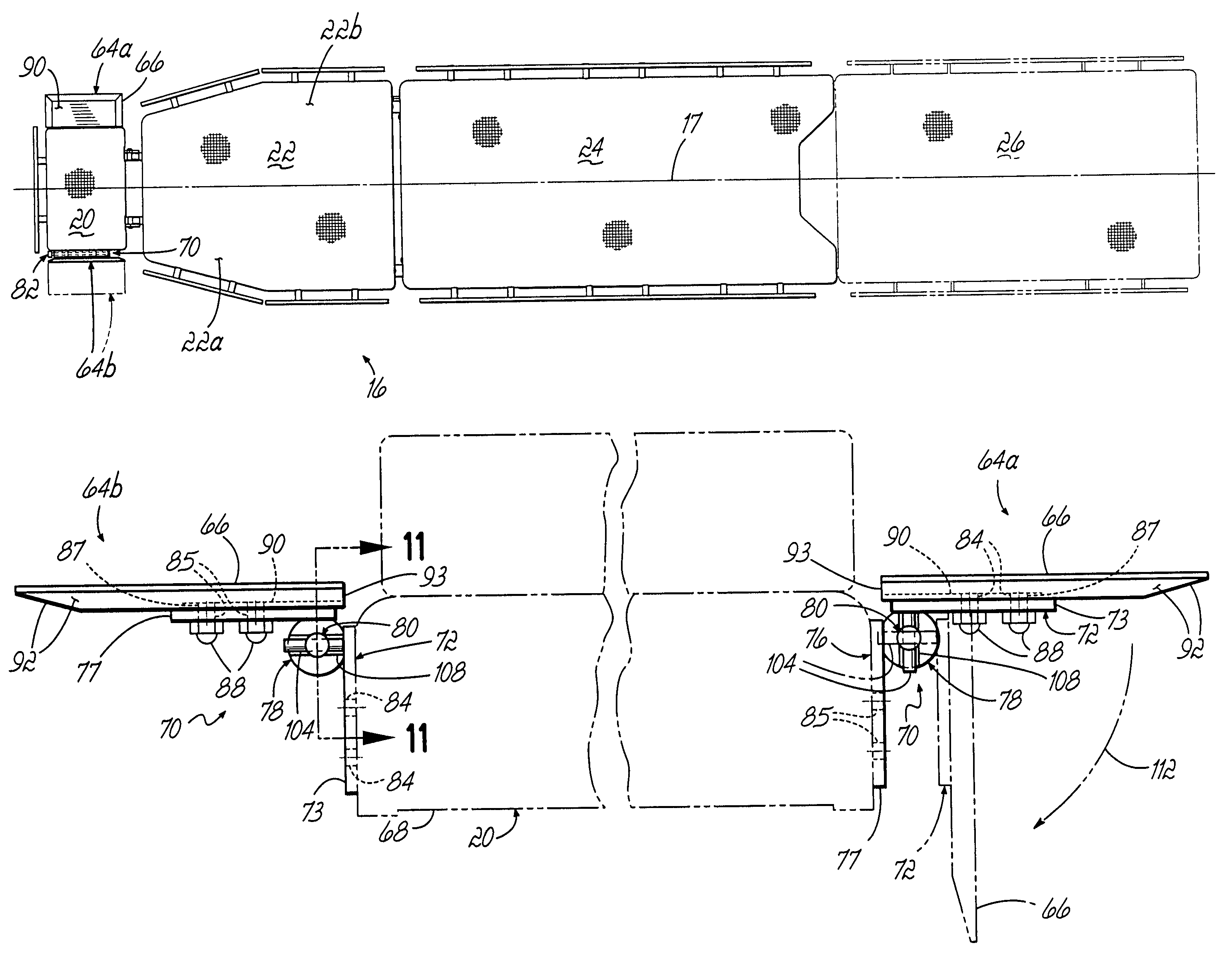
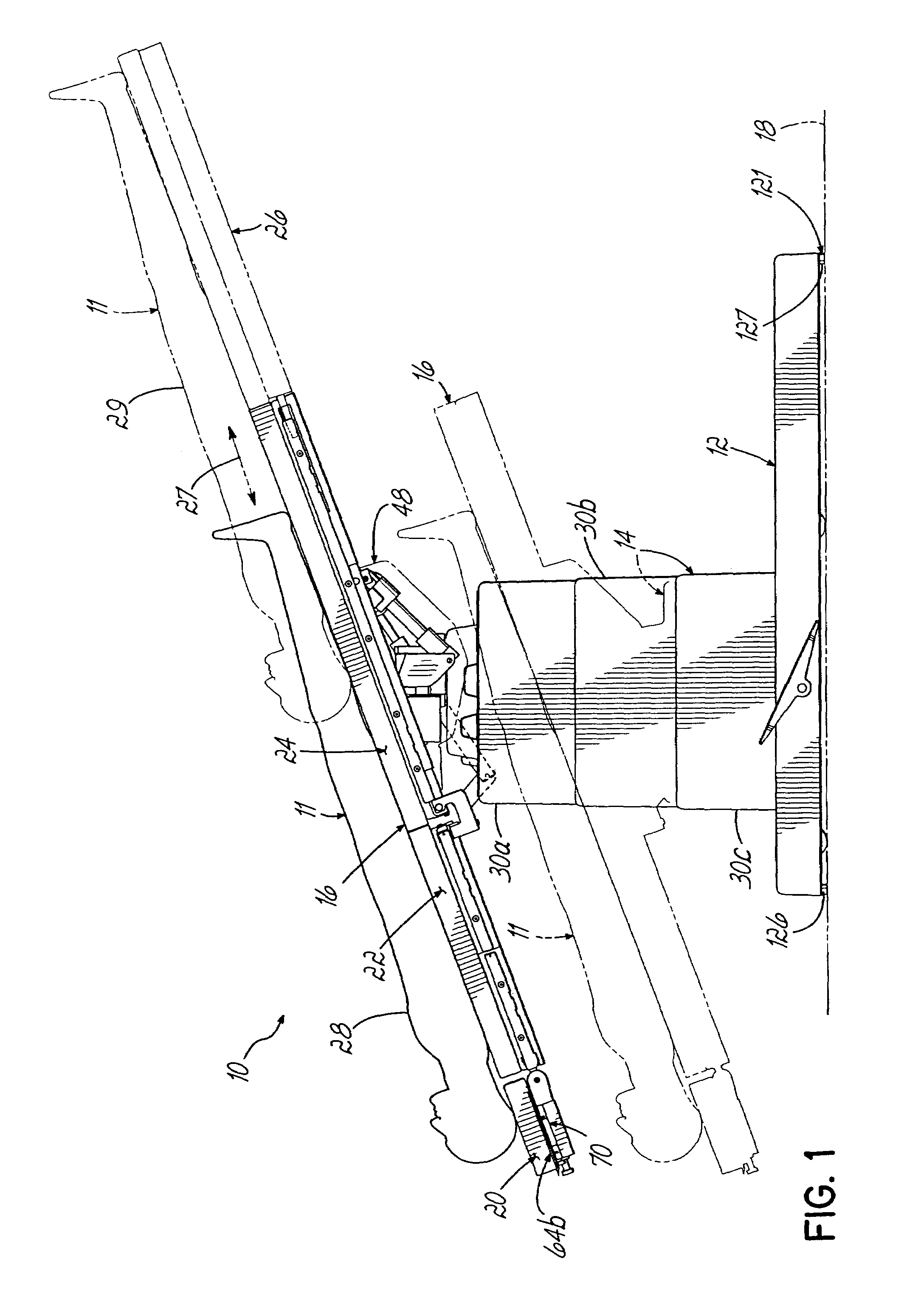
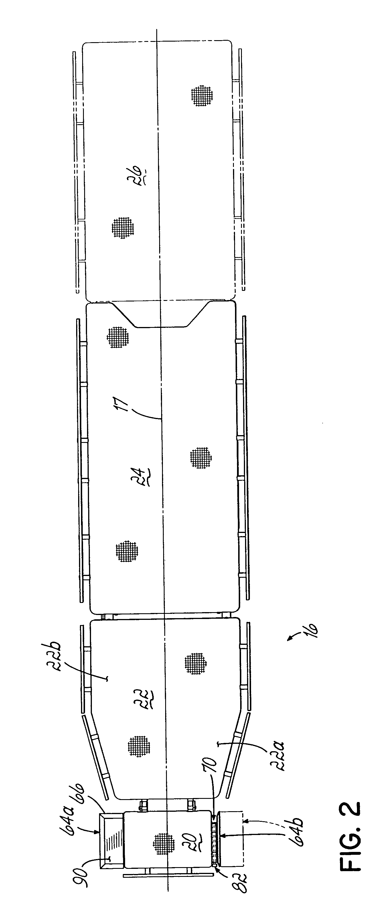
[0029]With reference to FIG. 1, a surgical table 10 of the present invention is shown with a patient 11 resting in a supine position. To serve as positional references hereinafter, the surgical table 10 shall be described as being “longitudinal” along its length and as being “transverse” across its width. The longitudinal end of the surgical table shown to the left in FIGS. 1 and 2 shall be referred to as the “head.” The longitudinal end of the surgical table shown at the right in FIGS. 1 and 2 shall be termed its “foot.” The transverse side of the surgical table facing the viewer in FIG. 1 shall be referred to as the “rear” and the opposite transverse side shall be referred to as the “front.” The terms “head,”“foot,”“front,” and “rear” shall be used hereinafter in a relative sense to assist in understanding the features and positions of the various elements of the surgical table but are not intended to be limiting of the present invention.

[0030]With reference to FIGS. 1 and 2, the ...


PUM


Abstract

A surgical table which includes a patient support surface and one or more trays pivotally connected to the patient support surface and selectively deployed to hold objects such as surgical instruments. Each tray has a first condition in which angular rotation of the tray about the axis of rotation is inhibited and a second condition in which the tray is rotatable angularly about the axis of rotation. In the first condition, the tray is capable of receiving and supporting the surgical instruments. This also permits a width reduction of the back section of the patient support surface.

Description

CROSS-REFERENCE TO RELATED APPLICATIONS[0001]This application is a divisional of application Ser. No. 10 / 068,592, filed Feb. 5, 2002 and now U.S. Pat. No. 6,721,976, the disclosure of which is fully incorporated herein by reference.FIELD OF THE INVENTION[0002]The present invention generally relates to apparatus for supporting patients during medical procedures and, more specifically, to surgical tables having improved patient access and a stable floor locking mechanism.BACKGROUND OF THE INVENTION[0003]Conventional surgical and medical tables are designed to provide a support platform for holding patients in an appropriate position during surgery or a procedure. Floor space in hospital and out-patient operating rooms is at a premium. Therefore, the design of the surgical table must afford surgical team members ready access to various body parts of the patient from various locations along the table before, during or after the surgical or medical procedure and yet minimize the amount o...

Claims


Application Information

Patent Timeline
Patent Type & Authority Patents(United States)
IPC IPC(8): A61G13/04A61G13/00A61G13/10
CPCA61G13/04A61G13/10Y10T16/54028A61G13/129
Inventor SCHWAEGERLE, GARY G.
Owner RELIANCE MEDICAL PRODS
Why Eureka
Try Eureka