Investment casting cores

a technology of investment casting and cores, applied in the field of investment casting, can solve the problems of difficulty in manufacturing fine features, high cost of engine efficiency,

Inactive Publication Date: 2005-08-16
RTX CORP
View PDF9 Cites 173 Cited by
  • Summary
  • Abstract
  • Description
  • Claims
  • Application Information

AI Technical Summary

Problems solved by technology

Such cooling comes with an associated cost in engine efficiency.
The fine features may be difficult to manufacture and / or, once manufactured, may prove fragile.

Method used


Image

  • Investment casting cores
  • Investment casting cores
  • Investment casting cores

Examples


Embodiment Construction

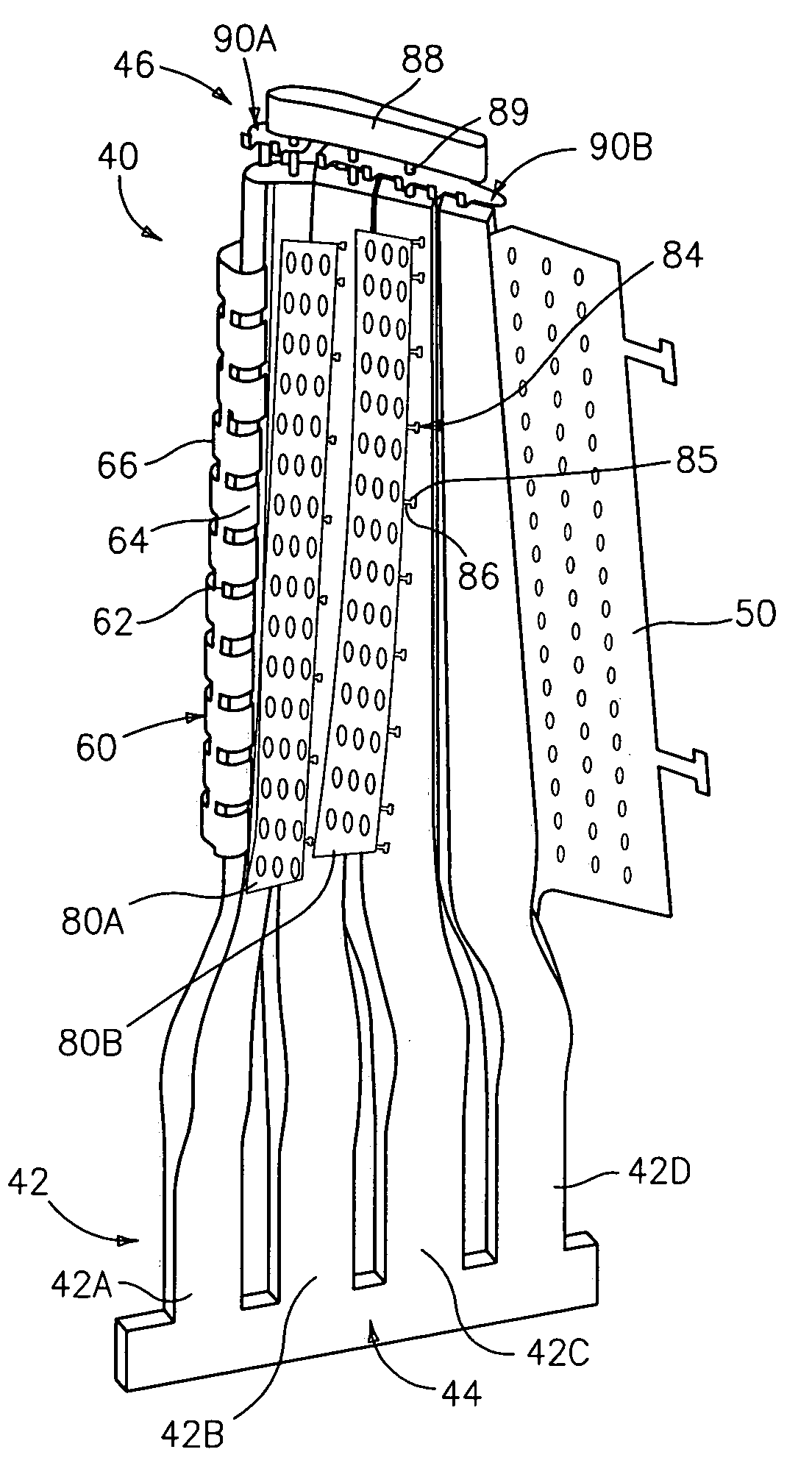
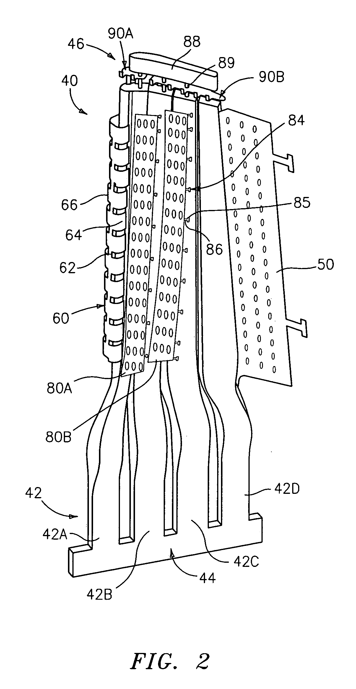
[0038]FIG. 2 shows a blade-forming core 40 including a ceramic feed core 42. The ceramic feed core 42 may be formed in one or more pieces and may provide one or more passageways within the ultimate blade. In the exemplary embodiment, the feed core 42 has four main portions 42A–42D extending from a root area 44 to a tip area 46. In the exemplary embodiment, the leading and trailing portions 42A and 42D are separate from the middle portions 42B and 42C along a portion of the feed core associated with the airfoil of the blade. The core 40 further includes one or more refractory metal core (RMC) elements secured to the feed core portions. In the exemplary embodiment, a trailing RMC 50 extends from a leading edge embedded in a slot within a trailing region of the trailing feed core portion 42D to a trailing edge and has first and second surfaces associated with pressure and suction sides of the airfoil to be formed. In the exemplary embodiment, the trailing RMC 50 forms a trailing edge o...


PUM

PropertyMeasurementUnit
draft angleaaaaaaaaaa

Abstract

A sacrificial core for forming an interior space of a part includes a ceramic core element and a first core element including a refractory metal element. The ceramic core element may be molded over the first core element or molded with assembly features permitting assembly with the first core element.

Description

BACKGROUND OF THE INVENTION[0001](1) Field of the Invention[0002]The invention relates to investment casting. More particularly, it relates to the investment casting of superalloy turbine engine components.[0003](2) Description of the Related Art[0004]Investment casting is a commonly used technique for forming metallic components having complex geometries, especially hollow components, and is used in the fabrication of superalloy gas turbine engine components. The invention is described in respect to the production of particular superalloy castings, however it is understood that the invention is not so limited.[0005]Gas turbine engines are widely used in aircraft propulsion, electric power generation, and ship propulsion. In gas turbine engine applications, efficiency is a prime objective.[0006]Improved gas turbine engine efficiency can be obtained by operating at higher temperatures, however current operating temperatures in the turbine section exceed the melting points of the supe...

Claims


Application Information

Patent Timeline
Patent Type & Authority Patents(United States)
IPC IPC(8): B22C7/00B22C9/24B22C7/02B22C9/04B22C9/22B22C9/10F01D25/00F02C7/00
CPCB22C7/02B22C21/14B22C9/103B22C9/04
Inventor BEALS, JAMES T.DRAPER, SAMUEL D.LOPES, JOSE A.MURRAY, STEPHEN D.SPANGLER, BRANDON W.TURKINGTON, MICHAEL K.DUBE, BRYAN P.SANTELER, KEITH A.SNYDER, JACOB A.
Owner RTX CORP
Why Eureka
Try Eureka