Human interface method and apparatus

Inactive Publication Date: 2005-08-16
TAMADA KEN
View PDF21 Cites 26 Cited by
  • Summary
  • Abstract
  • Description
  • Claims
  • Application Information

AI Technical Summary

Benefits of technology

[0010]These and other important aspects of the present inventi

Problems solved by technology

These types of computer input devices cannot determine information about a computer user and then automatically input the information but instead rely upon the operator to manually enter all information.
Another problem with conventional computer input devices is that they cannot automatically enter sensory information into a computer re

Method used


Image

  • Human interface method and apparatus
  • Human interface method and apparatus
  • Human interface method and apparatus

Examples


Embodiment Construction

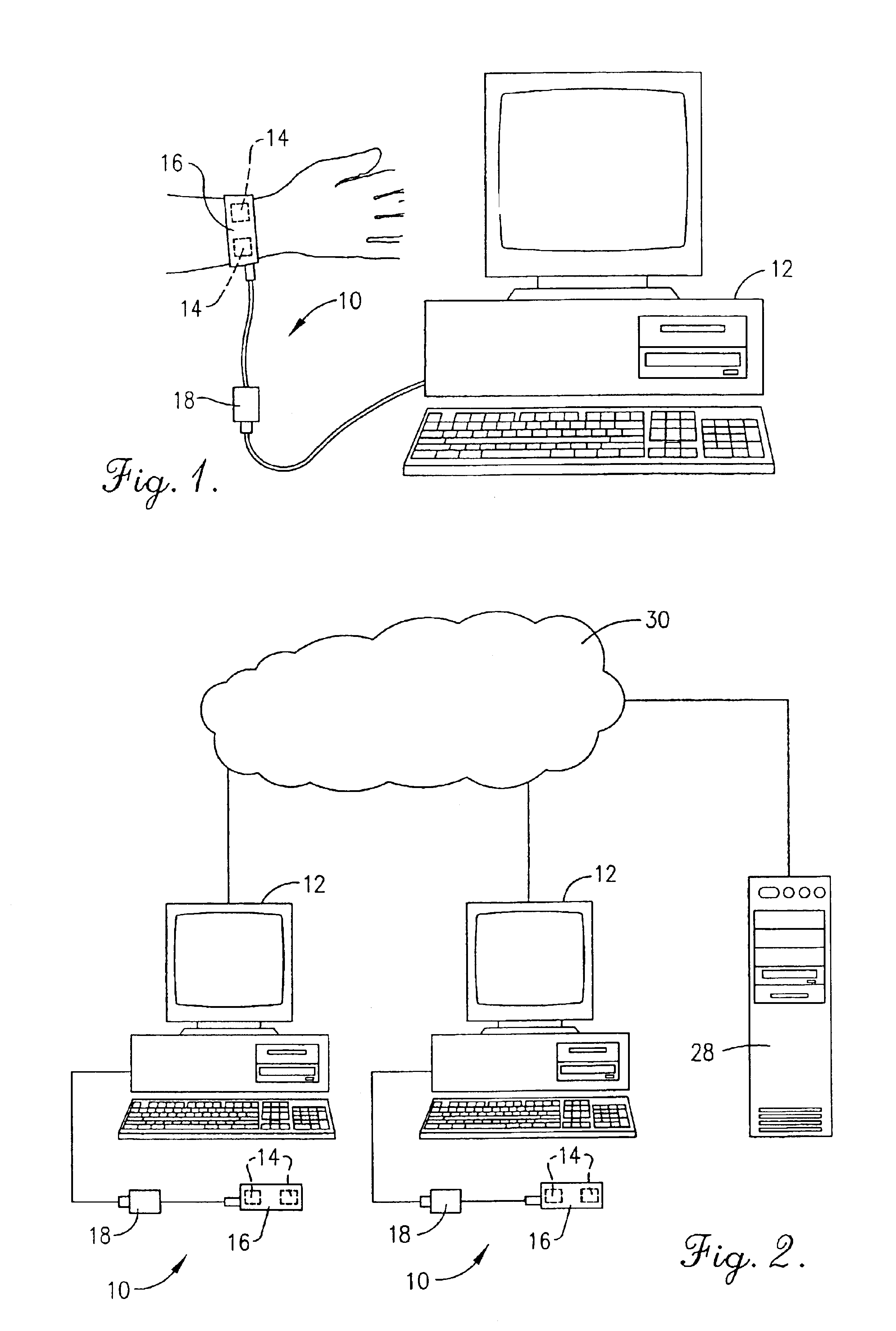
[0016]Turning now to the drawing figures, and particularly FIG. 1, the present invention broadly includes a human interface device 10 and a computer program that may be run on a computer 12 such as the one illustrated. The human interface device 10 measures one or more physical conditions of a computer operator and automatically inputs signals corresponding to the physical conditions into the computer 12. The computer program then analyzes the signals to control certain aspects of other computer programs run by the computer 12 or for monitoring purposes as described in more detail below. The signals may also be used to permit computer users to interact with other remote computer users via a communications network.

[0017]The human interface device 10 includes one or more sensors 14, a carrier 16 that permits the sensors to be worn by an operator of the computer 12, and a computer interface 18 for coupling the sensors with the computer 12. The sensors 14 may be any commercially availab...


PUM


Abstract

A method and apparatus for measuring one or more physical conditions of a computer operator and for automatically inputting signals corresponding to the physical conditions into a computer (12) for control and monitoring purposes.

Description

CROSS REFERENCE TO RELATED APPLICATION[0001]This application is a Continuation in Part of U.S. Pat. No. 09 / 567,176 titled “Human Interface Method and Apparatus” whose inventor is Ken Tamada, which was filed on May 8, 2000, now abandoned.BACKGROUND OF THE INVENTION[0002]1. Field of the Invention[0003]The present invention relates to computer interface devices and methods. More particularly, the invention relates to a method and apparatus for measuring one or more physical conditions of a person and inputting signals corresponding to the physical conditions into a computer for control and monitoring purposes and for permitting computer users to interact with other remote computer users via a communications network.[0004]2. Description of the Prior Art[0005]Many computer programs are designed for use by computer operators having different levels of experience or knowledge. For example, many computer games have different “levels” or speeds that accommodate players of different skill lev...

Claims


Application Information

Patent Timeline
IPC IPC(8): G06F3/00A61B5/00A63F13/00A61B5/145A63F13/10G06F3/01
CPCG06F3/011
Inventor TAMADA, KEN
Owner TAMADA KEN
Why Eureka
Try Eureka