Germicidal lamp retaining assembly

a technology of germicidal lamps and assembly parts, which is applied in the field of ultraviolet light fixtures, can solve the problems of relatively short use of ultraviolet lamps

Inactive Publication Date: 2005-08-23
DUST FREE
View PDF11 Cites 25 Cited by
  • Summary
  • Abstract
  • Description
  • Claims
  • Application Information

AI Technical Summary

Problems solved by technology

Further, mounting a linear UV lamp perpendicular to the fins may result in the use of a relatively short UV lamp, which will not emit as much UV energy as would a longer lamp.

Method used


Image

  • Germicidal lamp retaining assembly
  • Germicidal lamp retaining assembly
  • Germicidal lamp retaining assembly

Examples


Embodiment Construction

[0024]The present invention is best understood in relation to FIGS. 1-7 of the drawings, like numerals being used for like elements of the various drawings.

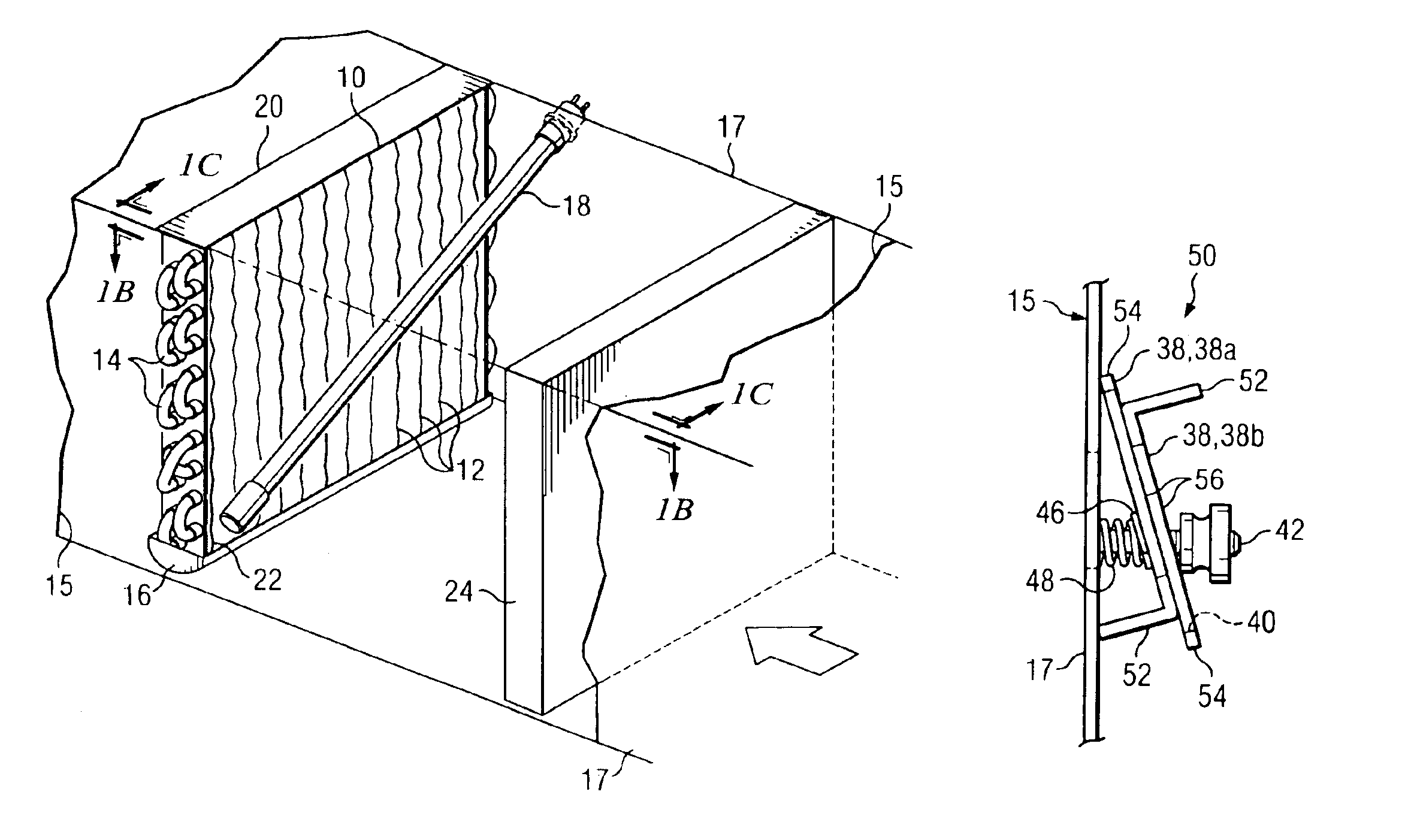
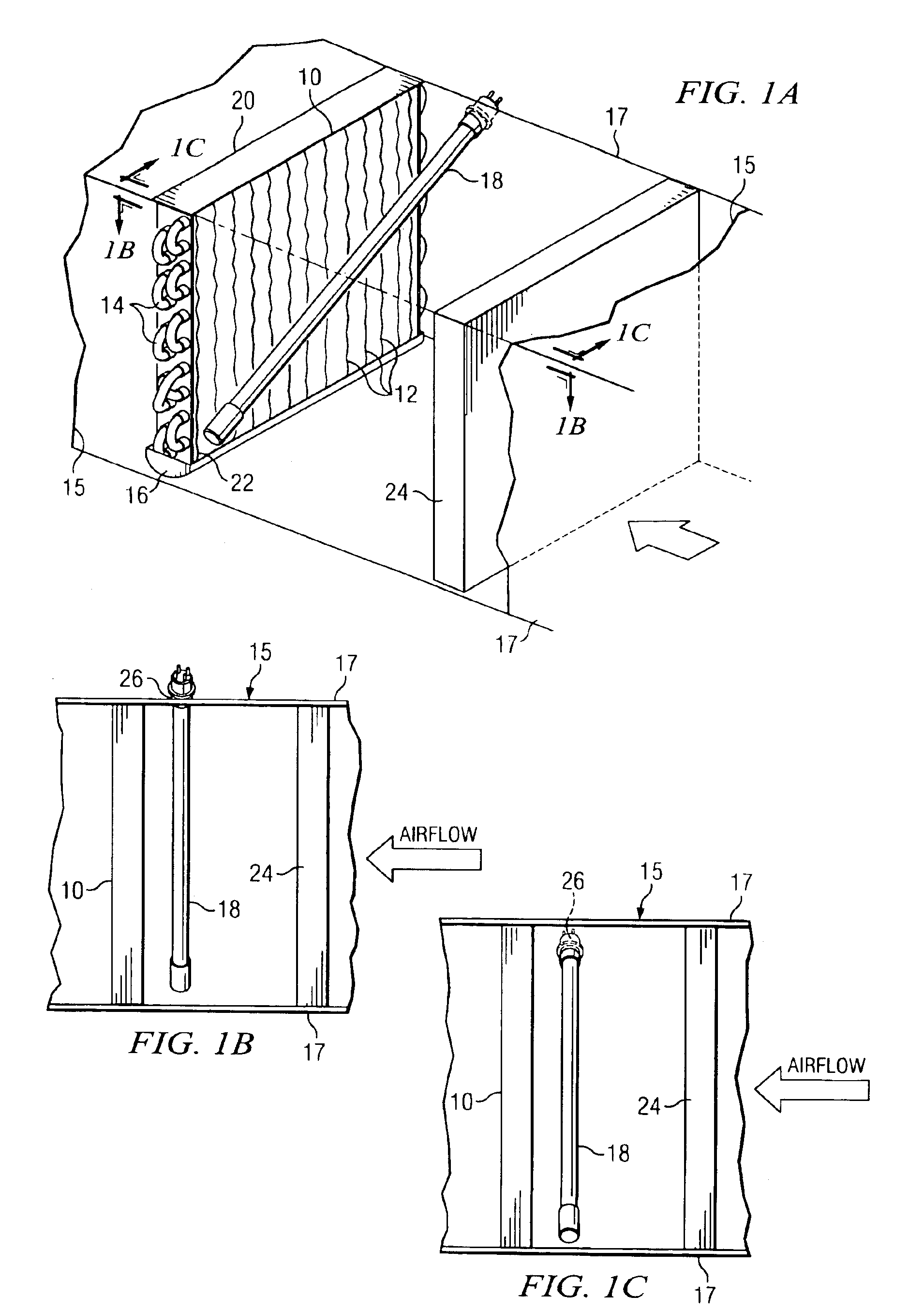
[0025]FIG. 1a illustrates a generalized perspective view of the present invention. A coil 10, having fins 12 and coolant exchange tubes 14, is disposed in a duct 15 of an air conditioning system. A drain pan 16 is disposed below the coil, such that condensation from the coil 10 flows into the drain pan 16. A germicidal lamp 18 is disposed between a first position near an upper corner 20 of the coil 10 and a second position near opposite lower corner 22. Airflow is shown as passing through a filter 24, which typically precedes the coil 10 in the direction of the airflow. Generally, the airflow is produced by a blower motor (not shown). The blower motor is often placed between the coil 10 and filter 22, although it could also be placed before the filter or after the coil. The relative order of the blower motor, filter 24 and coil 2...


PUM


Abstract

An angled germicidal lamp is used to illuminate a coil and drain pan for optimum energy utilization. An angled mount formed of two retention clips positions a germicidal lamp at a desired angle. A security access cover ensures that the germicidal lamp is disconnected from its power supply before access. Multiple germicidal lamps may be mounted by a single retention clip.

Description

CROSS-REFERENCE TO RELATED APPLICATIONS[0001]This application is a continuation-in-part of U.S. Pat. No. 6,539,727 (U.S. Ser. No. 10 / 026,167) filed Dec. 21, 2001 to Burnett, issued Apr. 1, 2003, entitled “Angled UV Fixture”.STATEMENT OF FEDERALLY SPONSORED RESEARCH OR DEVELOPMENT[0002]Not ApplicableBACKGROUND OF THE INVENTION[0003]1. Technical Field[0004]This invention relates in general to air conditioning systems and, more particularly, to ultraviolet light fixtures.[0005]2. Description of the Related Art[0006]Over the last several years, the use of ultraviolet (UV) light in commercial and residential air conditioning applications has become more popular. A UV light source in the UV-C spectrum, specifically at 253.7 nm, and potentially UV light in other frequencies such as 187 nm, has been shown to be extremely effective in destroying bacteria and fungi in air conditioning systems.[0007]During operation of an air-conditioning system, water condenses on the heat exchanger (typicall...

Claims


Application Information

Patent Timeline
Patent Type & Authority Patents(United States)
IPC IPC(8): F24F3/16F24F8/22
CPCF24F3/16F24F2003/1667F24F8/22
Inventor BURNETT, GREGGBURK, THOMAS K.
Owner DUST FREE
Why Eureka
Try Eureka