Milking and application teat cup, system, and method

a technology of teat cups and teat cups, applied in the field of animal milking systems and methods, can solve the problems of clinging to the teat surface, reducing the economic and environmental effect of use, and reducing the effect of fluid use during the application process

Inactive Publication Date: 2005-08-30
DELAVAL INC
View PDF29 Cites 72 Cited by
  • Summary
  • Abstract
  • Description
  • Claims
  • Application Information

AI Technical Summary

Benefits of technology

[0015]Another exemplary embodiment relates to a milking method including a combination milking and applicator device. The milking method includes commencing a milking session in which milk is delivered from animal teats engaged by a number of teat cups, pre-charging a fluid line coupled to the number of teat cups with a disinfecting or conditioning fluid or pausing before pre-charge to insure normal delivery of milk from teats, terminating the milking session, and dispensing the disinfectant and / or conditioning fluid from the fluid pre-charge out through applicators in the number of teat cups. The dispensing commences when the number of teat cups begin to disengage from the animal teats and the configuration between teat cups and teats is controlled or predictable.

Problems solved by technology

The vacuum suction is lost, and the cling of the liner surrounding the teat surface is broken.
Using too much fluid during the application process can have a negative economic and environmental effect.
Conversely, there is a negative economic and animal health influence created by using too little fluid or inconsistently or incorrectly applying it.
Converting the cleaning and / or disinfectant fluid or a substantial portion thereof into an aerosol, or converting its active sanitizing components or a portion thereof into a vapor through atomizing nozzles or other fractionation principles has negative environmental and human health effects.
As the elastic liner fatigues through use, the opening of the liner or mouthpiece, which forms the final vacuum seal around the animal's teat, can become misshapen.

Method used


Image

  • Milking and application teat cup, system, and method
  • Milking and application teat cup, system, and method
  • Milking and application teat cup, system, and method

Examples


Embodiment Construction

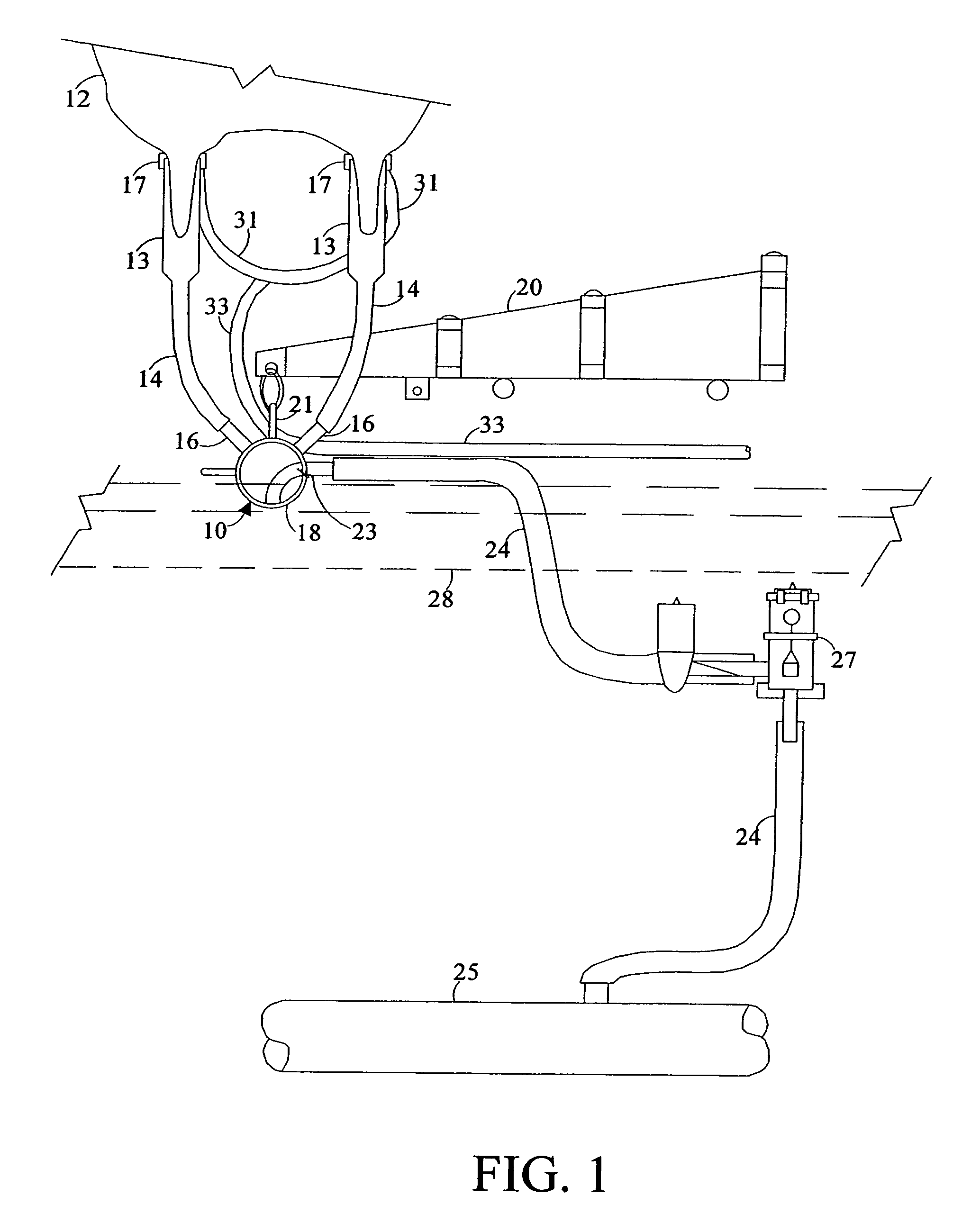
[0035]In reference to the drawings, a milking and applicator teat cup, system, and method in accordance with the invention are shown in conjunction with a portion of a milking system of the type utilized in automatic milking parlors. The milking system shown in FIG. 1 is oriented in position for milking a cow 12 with teat cups 13 attached to the teats of the udder. The milking system described with reference to FIG. 1 includes a side outlet milking claw for illustration purposes. Other milking system configurations can also include the milking and applicator teat cup. In the system, the milk is directed from the liners of the teat cups 13 through flexible milk tubes or “short milk hoses or tubes”14 through inlets 16 to a milking bowl 18 of a claw 10. The claw 10 is supported by a teat cup cluster support 20 that is connected to a hanger 21 of the milking claw. The milk exits from the bowl 18 of the claw through an outlet tube 23 to which a milk hose 24 is coupled. The milk hose 24 i...


PUM


Abstract

A milking and applicator teat cup is configured to receive an animal teat within a liner located in a shell. At the openings of the liner and shell where the teat is received, there is an applicator configured to dispense disinfectant, conditioning, and / or cleaning solution to the animal teat. The applicator is designed to discharge the solution horizontally across the openings of the liner and the shell. Such a teat cup can be integrated into a milking system having a valve manifold coupled to a number of teat cups and controlling flow of milk from the number of teat cups and flow of fluid to the applicators, and a controller including logic configured to provide control signals to the valve manifold. The controller signals the valve manifold to pre-charge a hose or line delivering fluid to the applicator and signals the valve manifold for the end of milking and begin delivery of the fluid from the applicator.

Description

FIELD OF THE INVENTION[0001]The present invention is related to animal milking systems and methods. More specifically, the present invention relates to a combination milking and cleaning teat cup, system and method.BACKGROUND OF THE INVENTION[0002]Various milking devices, systems, and methods have been developed that include a teat cup connected to a milking machine. Typically, the teat cup has a flexible inner lining and an inflexible outer shell. The inner lining or liner is commonly called an inflation. The teat cup operates to create a milking action by alternately reducing and increasing the pressure between the liner and the shell (a.k.a. “outside the liner”) while a constant reduced pressure is maintained between the liner and the teat (a.k.a. “inside the liner”). The alternating pressure between the liner and the shell can be adjusted using a vacuum producing source.[0003]Cleaning, disinfecting, and / or protecting the animal teats is an important part of the milking process. ...

Claims


Application Information

Patent Timeline
Patent Type & Authority Patents(United States)
IPC IPC(8): A01J5/00A01J5/08
CPCA01J5/08
Inventor WIPPERFURTH, STUARTKOLSTAD, RUSSELL
Owner DELAVAL INC
Why Eureka
Try Eureka