Metal gasket

Active Publication Date: 2005-08-30
MCCORD LEAKLESS SEALING
View PDF5 Cites 14 Cited by
  • Summary
  • Abstract
  • Description
  • Claims
  • Application Information

AI Technical Summary

Benefits of technology

[0008]The invention has the advantage of locating the bent tabs out of line with the neck regions of the tab portions. As such, when the gasket is clamped between two members to be sealed, such as a cylinder head and gasket, there is no direct line of stress back through the neck region that would result from clamping force applied to the laterally oriented bend tabs which might otherwise introduce a concentrated stress in the vicinity of the sealing bead th

Problems solved by technology

One disadvantage with such a structure is that when the gasket is clamped between a head and a block, clamping forces are applied to the bent tab region which are transmitted through the tab back to the stopper layer and can have the e

Method used


Image

  • Metal gasket
  • Metal gasket
  • Metal gasket

Examples


Embodiment Construction

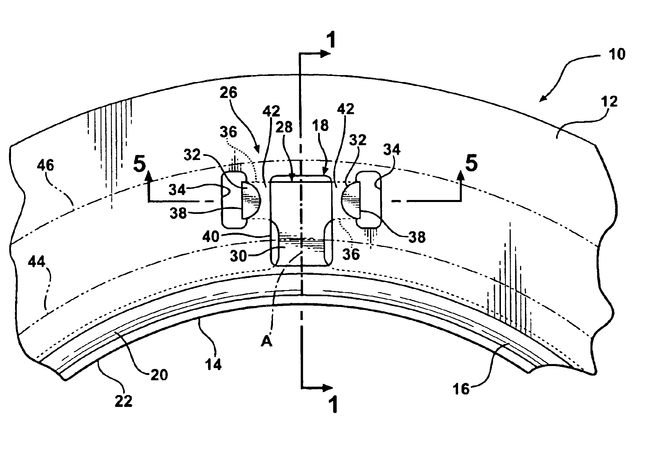
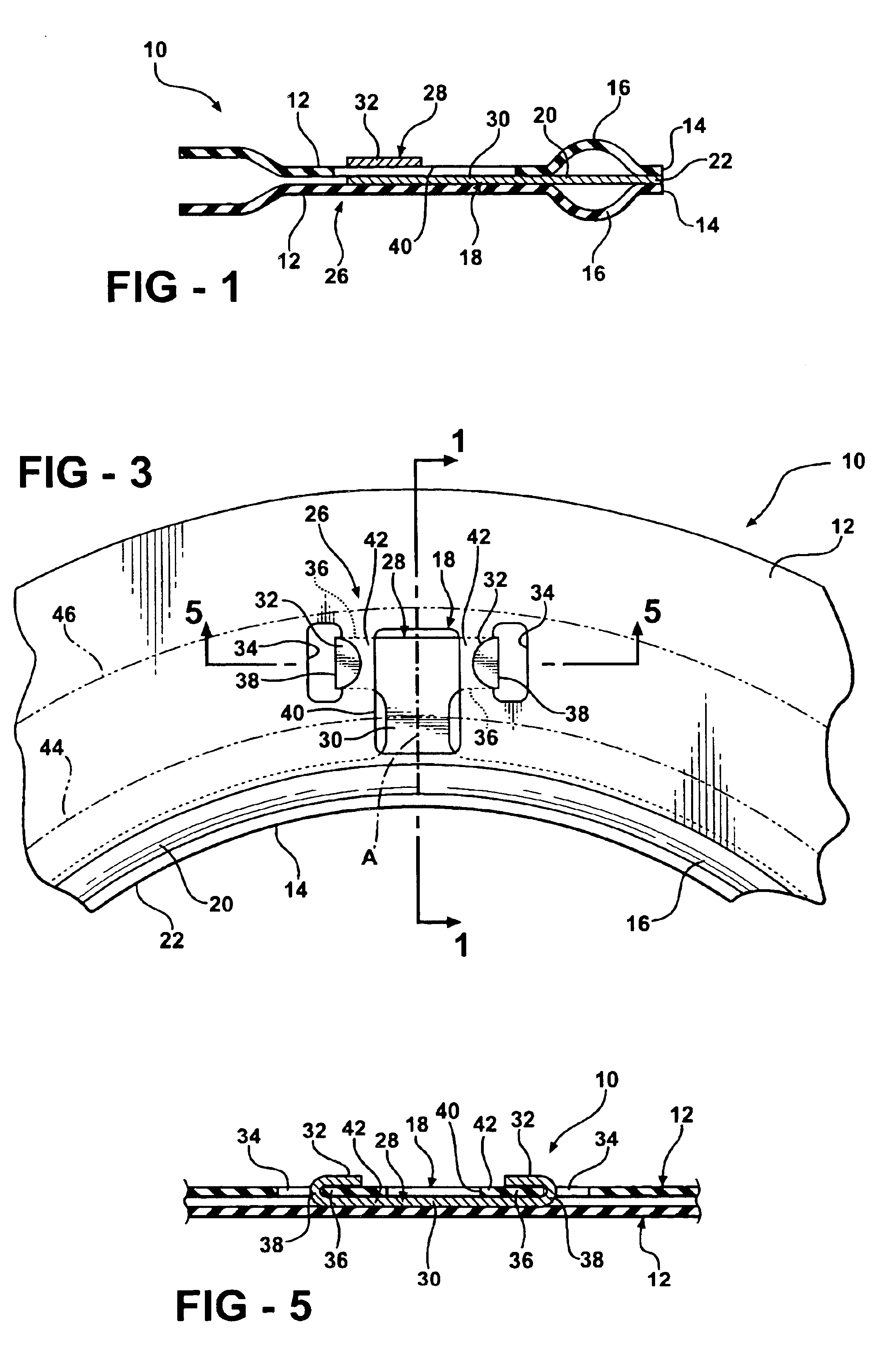
[0016]FIG. 1 is a cross-sectional view through a multi-layer metal gasket of the type used to seal one or more combustion chamber openings of an engine. The multi-layer gasket 10 is designed in the usual manner to be clamped between a cylinder head and engine block of an engine to seal the various passages communicating between the head and block, including one or more combustion chamber openings.

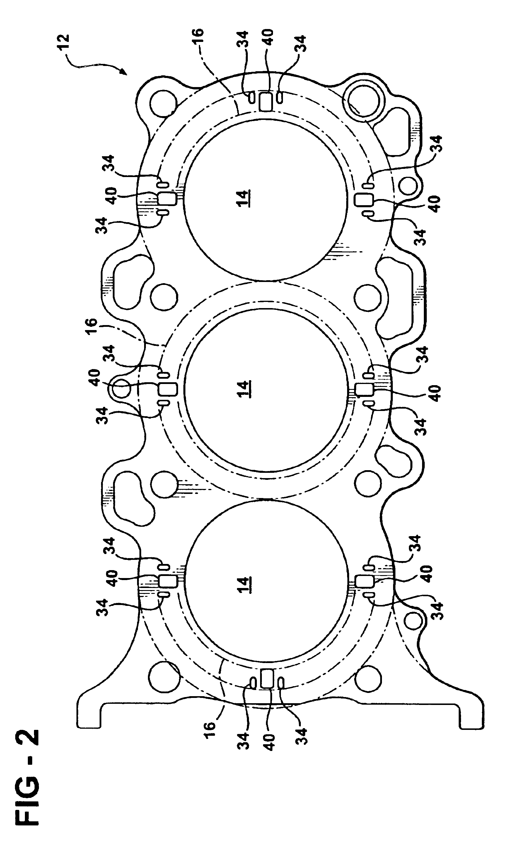
[0017]The gasket 10 includes at least one and preferably at least two resilient active layers 12 formed with at least one combustion chamber opening 14 sized and positioned to align with the combustion chamber of the engine. FIG. 2 is a plan view of the at least one active layer 12. In the disclosed embodiment, the active layer 12, and thus the gasket 10, is formed with three such combustion chamber openings 14.

[0018]As best shown in FIGS. 1 and 2, the outer active layers 12 of the gasket 10 are formed with a seal embossment 16 surrounding each combustion chamber openings 14. The seal embos...


PUM


Abstract

A multi-layer metal gasket includes at least on active layer and at least one shim layer having aligned combustion holes. The shim layer has annular portions surrounding the combustion holes and tab portions projecting radially outwardly from the annular portions surrounding the combustion holes. The annular portions underlie associated sealing beads of the active layer. The tab portions each have a radially extending neck region and a set of lateral bend tabs supported at the end of the neck region and projecting laterally outwardly thereof. The bend tabs project through an associated set of laterally spaced mounting windows formed in the active layer and are bent back toward one another to secure the shim layer to the active layer.

Description

[0001]This application claims the benefit of U.S. Provisional Application No. 60 / 432,876, filed Dec. 12, 2002.BACKGROUND OF THE INVENTION[0002]1. Technical Field[0003]This invention relates generally to multi-layered steel gaskets, and more particularly to the attachment of an intermediate stopper layer between adjacent active layers.[0004]2. Related Art[0005]U.S. Published application 2002 / 0135135 A1 discloses a metal gasket having an intermediate stopper layer disposed between two outer active layers and having a plurality of radial tab portions extending along a respective radial axis, and then bent out of the plane to extend through an associated window in one of the active layers and then further bent back upon itself in overlying relation to the active layer along the axis of the bend tab. One disadvantage with such a structure is that when the gasket is clamped between a head and a block, clamping forces are applied to the bent tab region which are transmitted through the tab...

Claims


Application Information

Patent Timeline
IPC IPC(8): F16J15/08
CPCF16J15/0831F16J2015/085F16J2015/0862F16J2015/0868F02F11/00F16J15/08
Inventor MATSUSHITA, YOSHITAKA
Owner MCCORD LEAKLESS SEALING
Why Eureka
Try Eureka