Retroreflective articles having moire-like pattern

a retro-reflective and pattern technology, applied in the field of retro-reflective articles having moire-like pattern, can solve problems such as moire-like pattern

Inactive Publication Date: 2005-08-30
3M INNOVATIVE PROPERTIES CO
View PDF37 Cites 38 Cited by
  • Summary
  • Abstract
  • Description
  • Claims
  • Application Information

AI Technical Summary

Benefits of technology

[0004]The present inventors have found that when very small cube-corner prisms are formed from a master having precisely positioned V-shaped intersecting grooves, retroreflective masters and retroreflective replicas thereof such as retroreflective sheeting exhibit a moiré-like pattern. It is surmised that the occurrence of such moiré-like pattern is caused from optical interference between neighboring cubes (i.e. group of cubes wherein the incident light is coherent). The presence of this moiré-like pattern in the sheeting is readily apparent and can be used for various traffic control, conspicuity, and document authentication uses, particularly for instances wherein the presence of the pattern is employed in such a manner that does not detract from the legibility.

Problems solved by technology

It is surmised that the occurrence of such moiré-like pattern is caused from optical interference between neighboring cubes (i.e. group of cubes wherein the incident light is coherent).

Method used


Image

  • Retroreflective articles having moire-like pattern
  • Retroreflective articles having moire-like pattern
  • Retroreflective articles having moire-like pattern

Examples


example 1

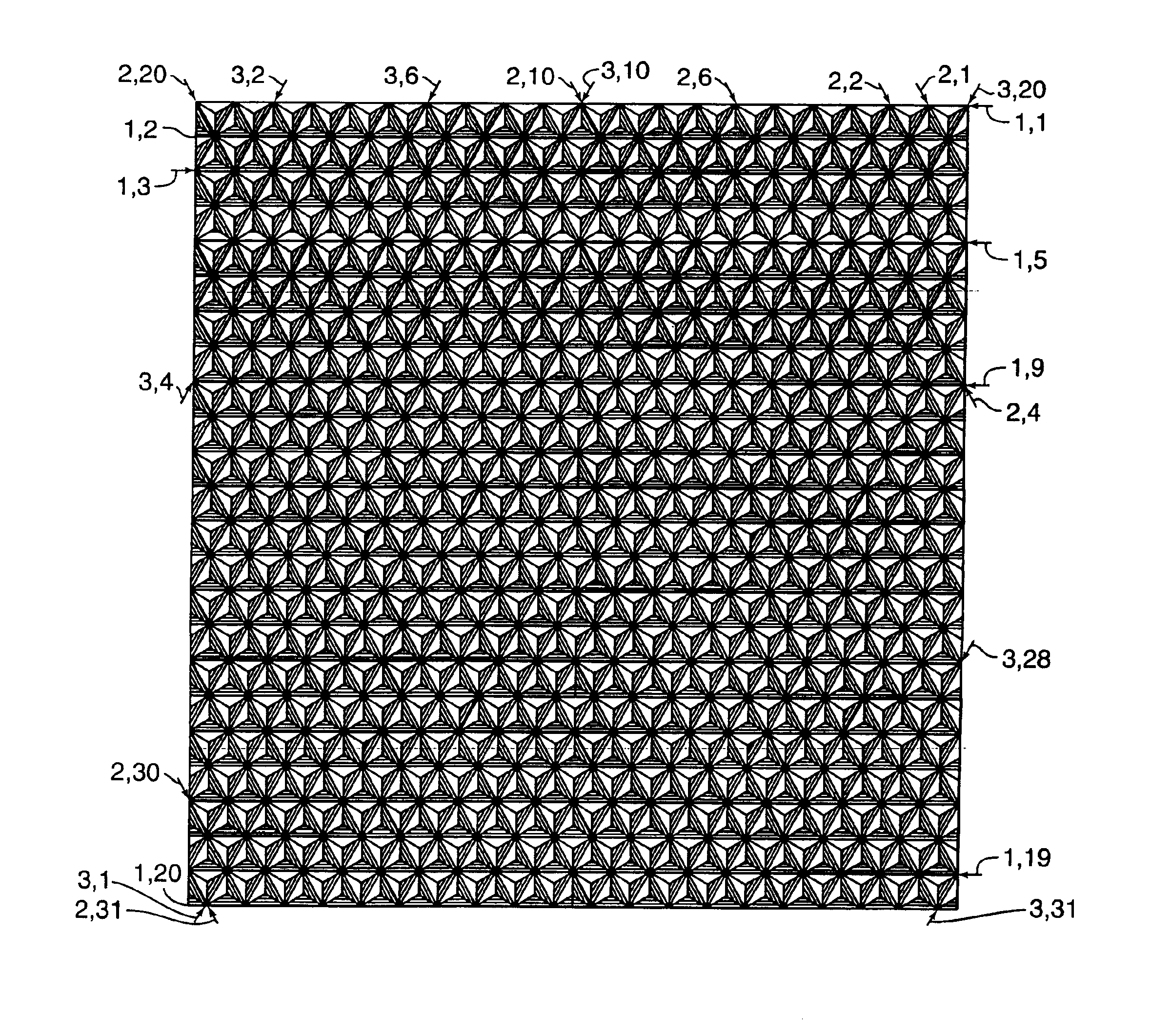
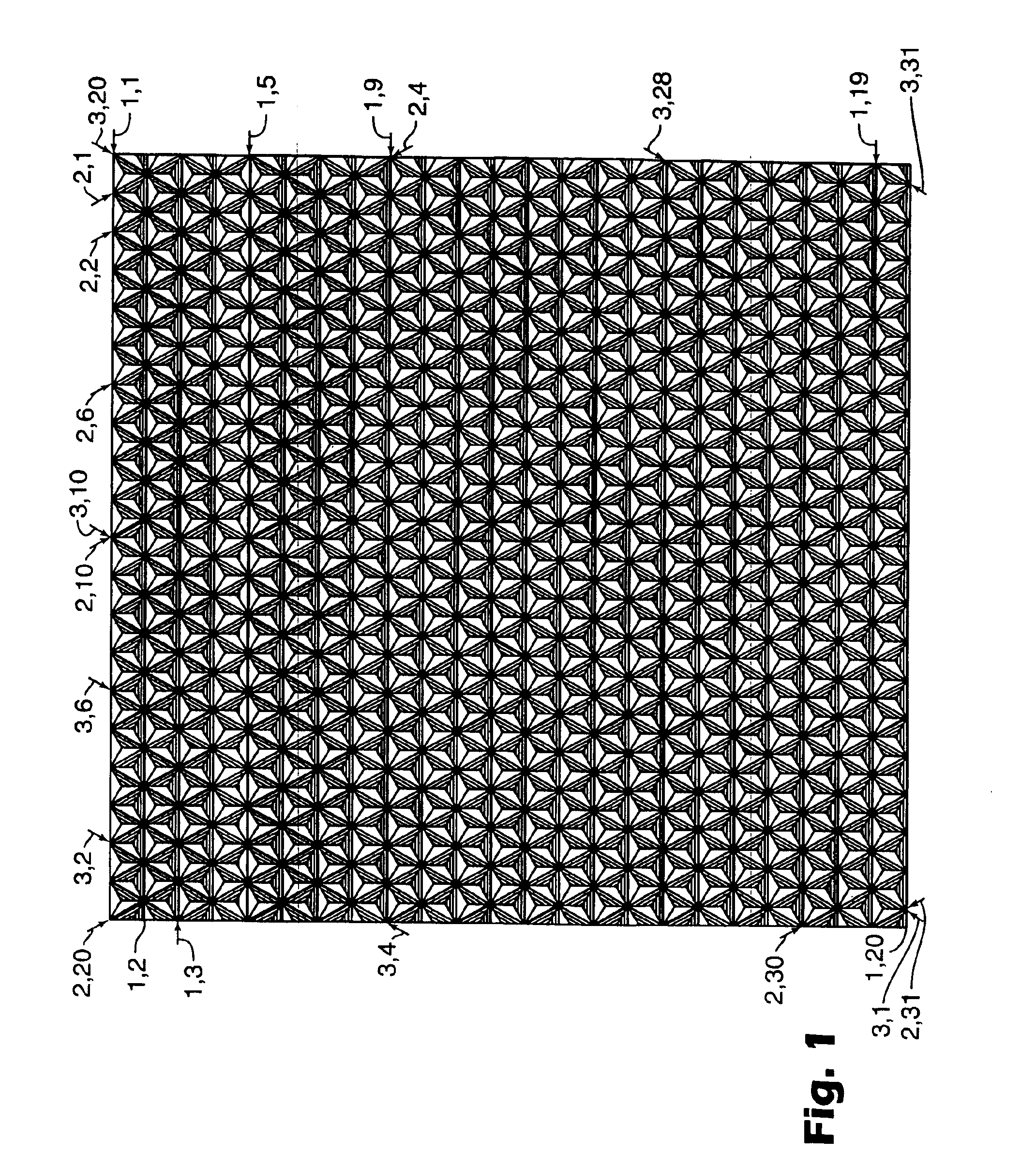
[0046]A master was prepared using a 9-inch (22.86 cm) diameter by about 1 inch thick block comprised of machinable metal. The block was machined to have a 4.75 inch (12.06 cm) square portion raised by about 0.005 inches (0.127 mm). The block was positioned on a groove-forming machine having a groove space and groove depth precision (i.e. point-to-point positioning) at least as precise as + / −100 nm and a resolution (i.e. ability of the laser interferometer positioning device to detect current axis position) of at least + / −10 nm.

[0047]Several diamond tools, which can be purchased from K&Y Diamond (Mooers, N.Y.) or Chardon Tool (Chardon, Ohio), were inspected to insure that each tool was suitable. Each diamond tool was evaluated with a 2000× white light microscope to insure that within 10 mils of the diamond tip the surface was scratch free. The surface finish of each diamond tool was also inspected by forming a test cut in a machinable substrate and evaluating the test cut with a micr...

example 2

[0052]The cube-corner surface of the retroreflective sheeting of Example A was coated with aluminum by vapor deposition at a thickness 950 angstroms

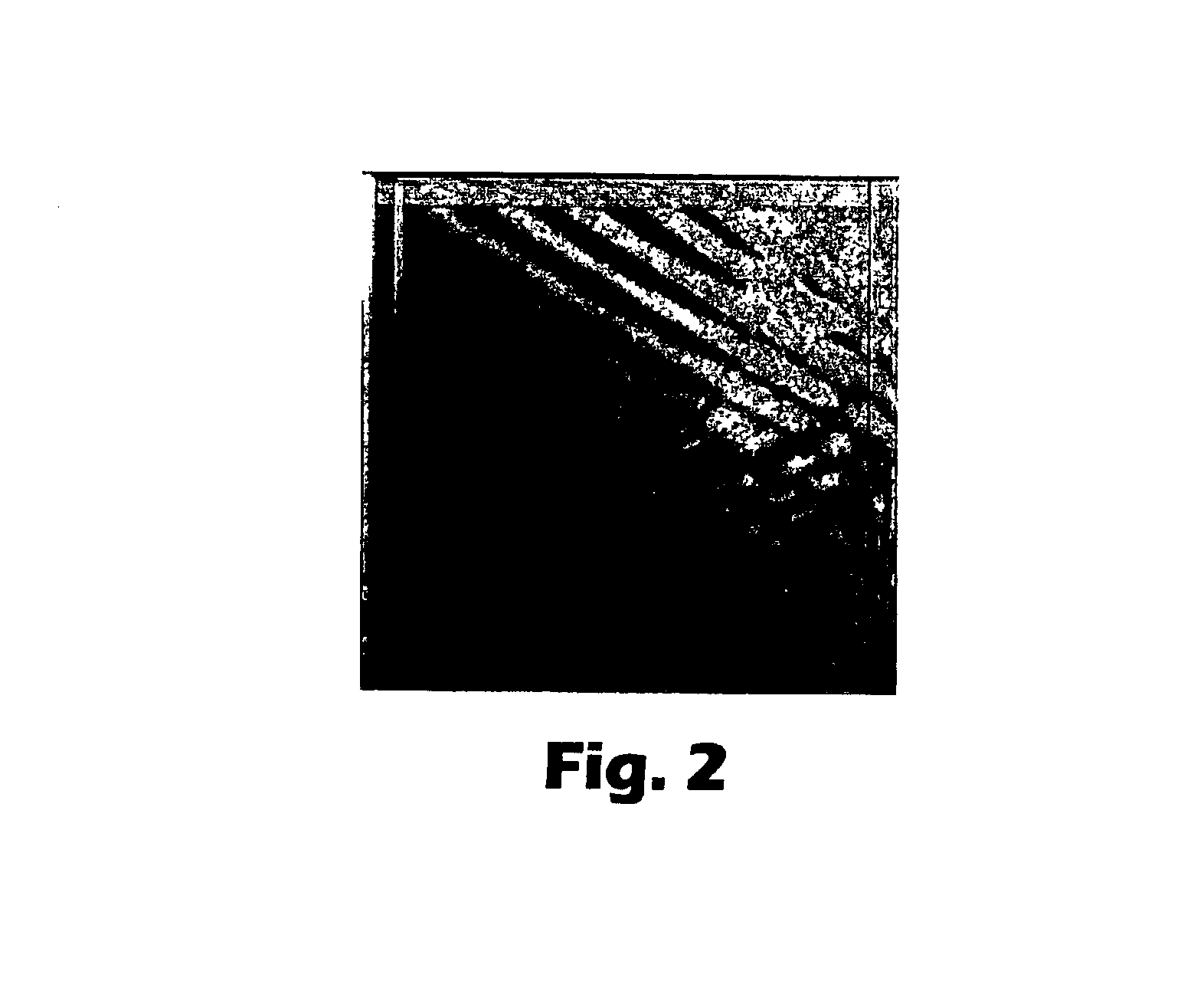
[0053]The resulting retroreflective sheeting was evaluated in the same manner as Example A. The light that retroreflected from the sheeting was observed to exhibit the moiré-like pattern. The coefficient of retroreflection, RA, was measured as recommended by CIE publication No. 54 at −4° entrance, 0° orientation, 0.2° observation. The average of 9 spot reading over the entire area of the sample was 1085 candela per lux per square meter with a standard deviation of 37 candela per lux per square meter.

example 3

[0054]A master was made in the same manner as described in Example A. A positive copy tooling was used to form sheeting from that tooling. The cube-corner structured surface of this negative copy sheeting was coated with aluminum by vapor deposition.

[0055]The resulting retroreflective sheeting was evaluated in the same manner as Example A. The light that retroreflected from the sheeting was observed to exhibit the moiré-like pattern. The coefficient of retroreflection, RA, was measured as recommended by CIE publication No. 54 at −4° entrance, 0° orientation, 0.2° observation. The average of 9 spot readings over the entire area of the sample was 1950 candela per lux per square meter with a standard deviation of 98 candela per lux per square meter.


PUM


Abstract

The invention relates to articles comprising a sheeting having a microstructured surface that reflects light in a moiré-like pattern. The invention further relates to methods of making a master and replicas thereof including tooling that results in sheeting having such pattern. A preferred method comprises forming V-shaped grooves in a substrate (e.g. metal plate) wherein the intersections of three grooves form cube-corner elements. The cube-corner elements are formed in such a manner that adjacent parallel grooves have substantially the same groove spacing and groove depth throughout the array. The master as well as corresponding tooling and sheeting preferably have a groove spacing within the range of about 0.0005 inches (0.0127 mm) to about 0.007 inches (0.1778 mm) throughout the array and more preferably a groove spacing of less than about 0.004 inches (0.1016 mm).

Description

FIELD OF THE INVENTION[0001]The invention relates to articles comprising a sheeting having a microstructured surface that reflects light in a moiré-like pattern. The invention further relates to methods of making a master and replicas thereof including tooling that results in sheeting having such pattern. A preferred method comprises forming V-shaped grooves in a substrate (e.g. metal plate) wherein the intersections of three grooves form cube-corner elements. The cube-corner elements are formed in such a manner that adjacent parallel grooves have substantially the same groove spacing and groove depth throughout the array. The master as well as corresponding tooling and sheeting preferably have a groove spacing within the range of about 0.0005 inches (0.0127 mm) to about 0.007 inches (0.1778 mm) throughout the array and more preferably a groove spacing of less than about 0.004 inches (0.1016 mm).BACKGROUND OF THE INVENTION[0002]Retroreflective cube-corner sheeting is commonly employ...

Claims


Application Information

Patent Timeline
Patent Type & Authority Patents(United States)
IPC IPC(8): G02B27/60G02B5/124G02B5/12
CPCG02B5/124G02B27/60
Inventor SEWALL, NELSON D.SMITH, KENNETH L.MEITZ, DAVID W.FLEMING, MADELEINE B.NELSON, JOHN C.
Owner 3M INNOVATIVE PROPERTIES CO
Why Eureka
Try Eureka