Device for monitoring area around vehicle

a technology for monitoring areas and vehicles, applied in anti-collision systems, non-deflectable wheel steering, underwater vessels, etc., can solve the problems of not providing driver with helpful information, driver is unable to know how close the vehicle is to the obstacle,

Inactive Publication Date: 2005-09-06
TOYOTA JIDOSHA KK +1
View PDF13 Cites 186 Cited by
  • Summary
  • Abstract
  • Description
  • Claims
  • Application Information

AI Technical Summary

Benefits of technology

[0007]In view of the foregoing problem, it is an object of the invention to provide a device for monitoring an area around a vehicle in which helpful information can be provided to the driver when backing up, without requiring an operation by the driver.
[0011]When the front wheels are in the second state when parallel parking, a state is created in which the front portion of the vehicle body will move significantly toward the parking space side. In this case, the front portion of the vehicle body is likely to contact an obstacle, such as a vehicle parked in front, that is in front of the parking space where the vehicle is to be parallel parked. According to this invention, however, when the front wheels have moved to the second state, a camera image of the side in front of the vehicle on the parking space side, i.e., a camera image of the area around the portion of the vehicle where the likelihood of contact with an obstacle when parallel parking the vehicle increases, is provided to the driver. Accordingly, helpful information is provided to the driver without requiring an operation by the driver.
[0014]Before the camera image of the area in front of the vehicle on the parking space side starts to be provided to the driver when parallel parking the vehicle, a camera image of the area to the back, as well as a camera image of the area to the side of the vehicle maybe provided to the driver, to further ensure safety when parallel parking.

Problems solved by technology

According to the foregoing device, however, the driver is only provided with information about whether the front portion of the vehicle has come near an obstacle.
As a result, the driver is unable to know how close the vehicle is to the obstacle.
Regarding this, the known device leaves the driver with the concern that the vehicle might contact the obstacle, and does not provide the driver with helpful information for backing the vehicle up safely.

Method used


Image

  • Device for monitoring area around vehicle
  • Device for monitoring area around vehicle
  • Device for monitoring area around vehicle

Examples


Embodiment Construction

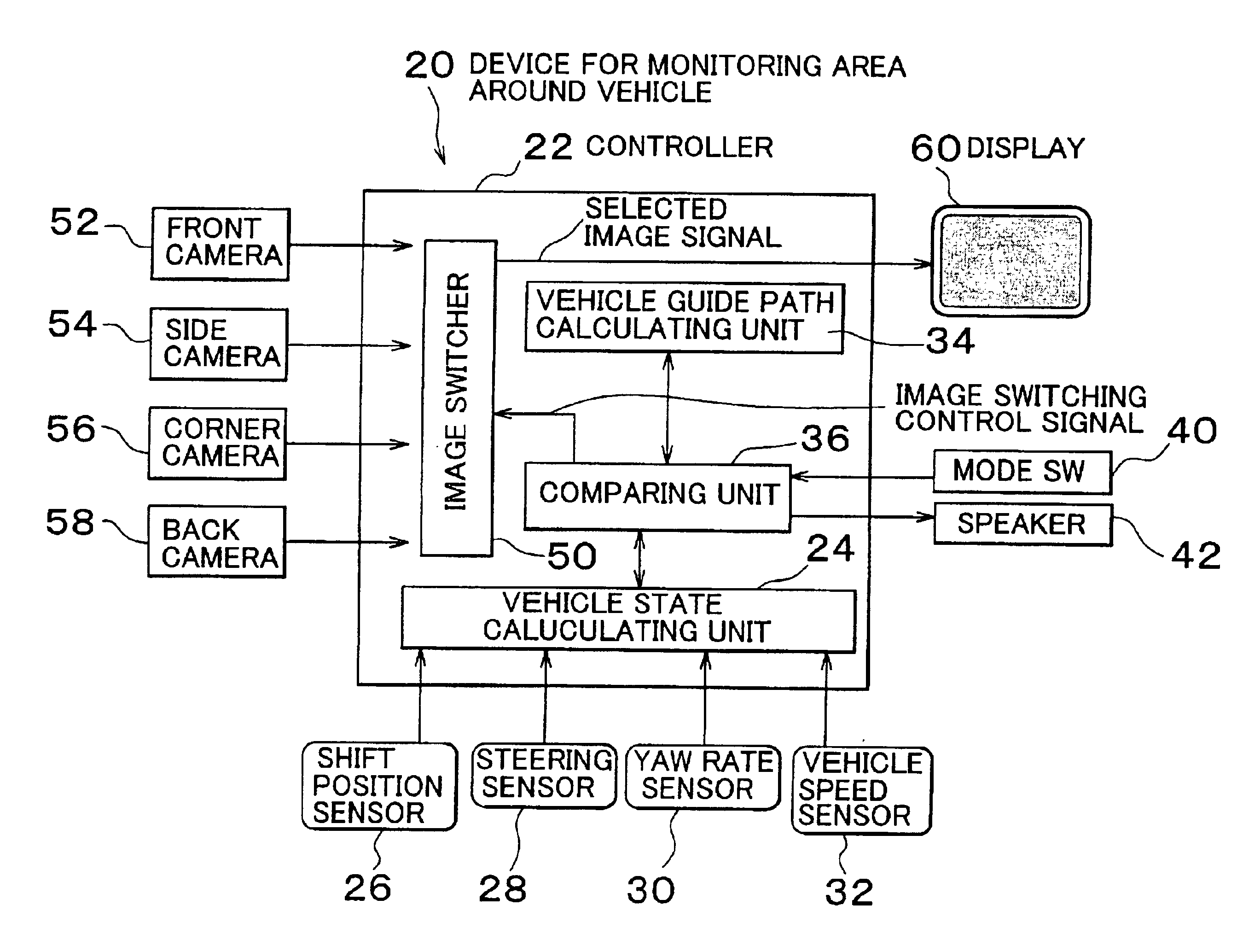
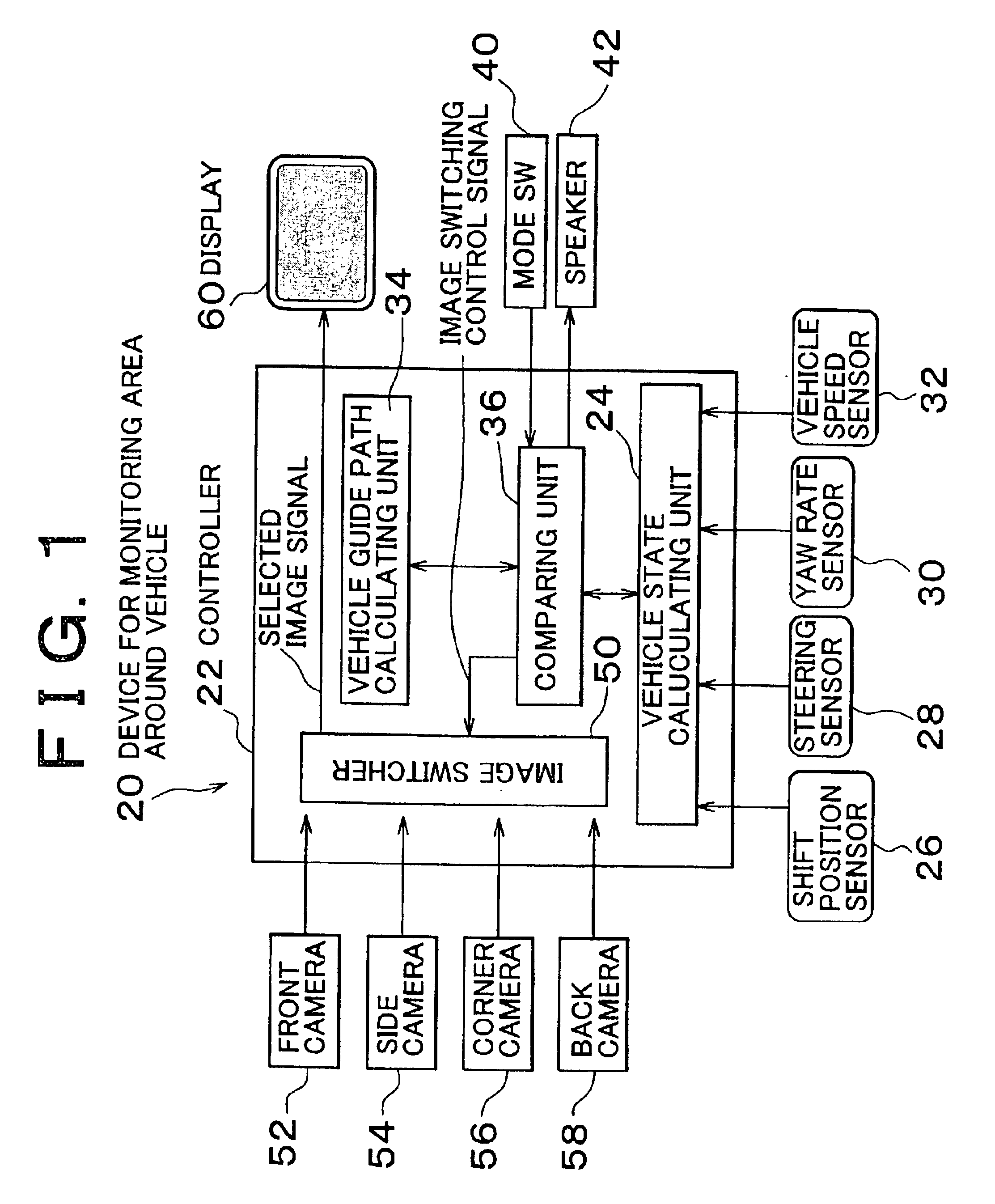
[0039]FIG. 1 is a system block diagram of a device 20 for monitoring an area around a vehicle, which is one exemplary embodiment of the invention. According to this exemplary embodiment, a vehicle in which the device (hereinafter referred to as “monitoring device”) 20 for monitoring an area around a vehicle has front wheels which function as steered wheels that are steered according to a steering operation by an occupant (e.g., a driver), and rear wheels which function as non-steered wheels. The monitoring device 20 includes an electronically controlled computer (hereinafter referred to as simply “controller”) 22 for monitoring, by which the monitoring device 20 is controlled.

[0040]The controller 22 houses a vehicle state calculating unit 24 that is connected to a shift position sensor 26, a steering angle sensor 28, a yaw rate sensor 30, and a vehicle speed sensor 32. The shift position sensor 26 generates a signal indicative of a position of a shift lever operated by the driver of...


PUM


Abstract

A back camera image from a back camera mounted on a rear portion of a vehicle body is displayed on a display mounted on the console inside the vehicle cabin when the vehicle is parallel parking. After the vehicle passes a steering direction reversal point in this state, a corner camera image from a corner camera mounted on a corner portion of a front portion of the vehicle body is displayed on the display when the vehicle nears a vehicle parked in front, or, more specifically, when an angle of the vehicle after it has reached the steering direction reversal point has reached a predetermined value. Guidance images may be overlaid upon the camera images during some or all of the parallel parking maneuver.

Description

INCORPORATION BY REFERENCE[0001]This disclosure of Japanese Patent Application No. 2001-335584 filed on Oct. 31, 2001 including the specification, drawing and abstract is incorporated herein by reference in its entirety.BACKGROUND OF THE INVENTION[0002]1. Field of the Invention[0003]The invention relates to a device for monitoring an area around a vehicle. More specifically, this invention relates to a device for monitoring an area around a vehicle, which is preferable for monitoring an area around the vehicle when parallel parking or backing up.[0004]2. Description of Related Art[0005]A device for monitoring an area around a vehicle, which displays an image of an area in back of the vehicle is displayed on a monitor screen when the vehicle backs up, has been known. An example of this kind of device is disclosed in Japanese Patent Laid-Open Publication No. 1-141137. This device is provided with an obstacle detecting sensor mounted on both sides at a front portion of the vehicle. The...

Claims


Application Information

Patent Timeline
Patent Type & Authority Patents(United States)
IPC IPC(8): B60R1/00H04N7/18B60R21/00
CPCB60R1/00B62D15/0275H04N7/181B60R2300/105B60R2300/302B60R2300/305B60R2300/70B60R2300/802B60R2300/806B60R2300/8086
Inventor TAKAGI, MAKOTOKATSUNO, TOSHIYASUKONNO, KAZUSHIKAKINAMI, TOSHIAKIIWATA, YOSHIFUMI
Owner TOYOTA JIDOSHA KK
Why Eureka
Try Eureka