Steering wheel

a steering wheel and steering wheel technology, applied in the direction of mechanical control devices, pedestrian/occupant safety arrangements, instruments, etc., can solve the problem that the switch operation portion is likely to protrude from the displaced ring plan

Inactive Publication Date: 2005-09-13
TOYODA GOSEI CO LTD
View PDF7 Cites 22 Cited by
  • Summary
  • Abstract
  • Description
  • Claims
  • Application Information

AI Technical Summary

Benefits of technology

[0008]It is an object of the present invention to provide a steering wheel capable of making the switch operation portion located on the front spoke portion follow the displacement of the ring plane smoothly.
[0016]In the steering wheel of the present invention, therefore, the switch operation portion located in the spoke is able to follow the displacement of the ring plane easily upon self-alignment. Moreover, the switch operation portion is prevented to the utmost from unnecessarily protruding from the ring plane, and applying partial pressure to the driver hitting the ring plane.
[0018]With this configuration, each of the front spoke cores includes two deformable portions, so that the displacement of the ring plane is promoted. By the second deformable portions, moreover, flexural strength of the deformable portions toward the boss portion (as will be called the first deformable portion, hereinafter) is improved while retaining the easiness of the displacement of the ring plane. Accordingly, deflection of the ring portion is suppressed. Consequently, natural frequency of the steering wheel itself is prevented from falling, thereby preventing chattering.

Problems solved by technology

However, if a core of the steering wheel with a switch operation portion is plastically deformed upon self-alignment, the switch operation portion is likely to protrude from the displaced ring plane.

Method used


Image

  • Steering wheel
  • Steering wheel
  • Steering wheel

Examples


Embodiment Construction

[0041]A preferred embodiment of the present invention is described below with reference to the accompanying drawings. However, the invention is not limited to the embodiment disclosed herein. All modifications within the appended claims and equivalents relative thereto are intended to be encompassed in the scope of the claims.

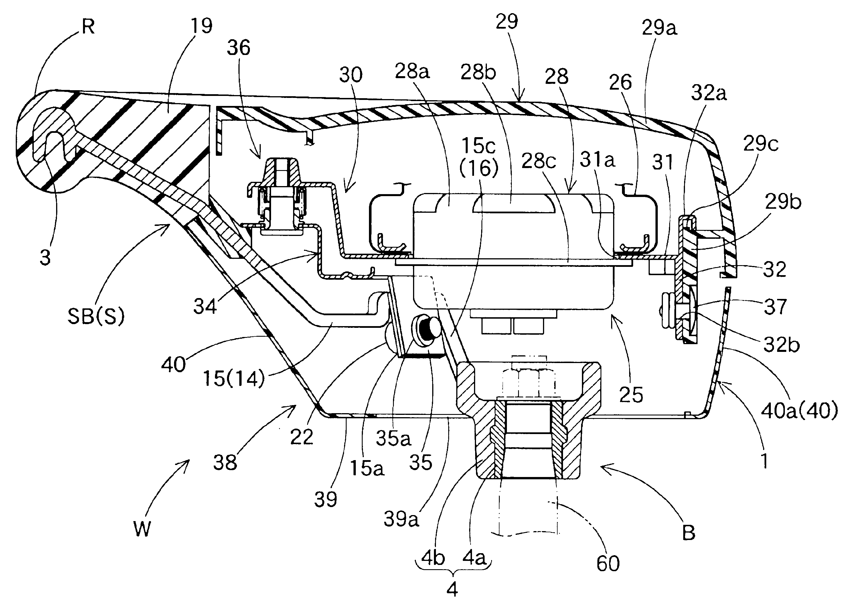
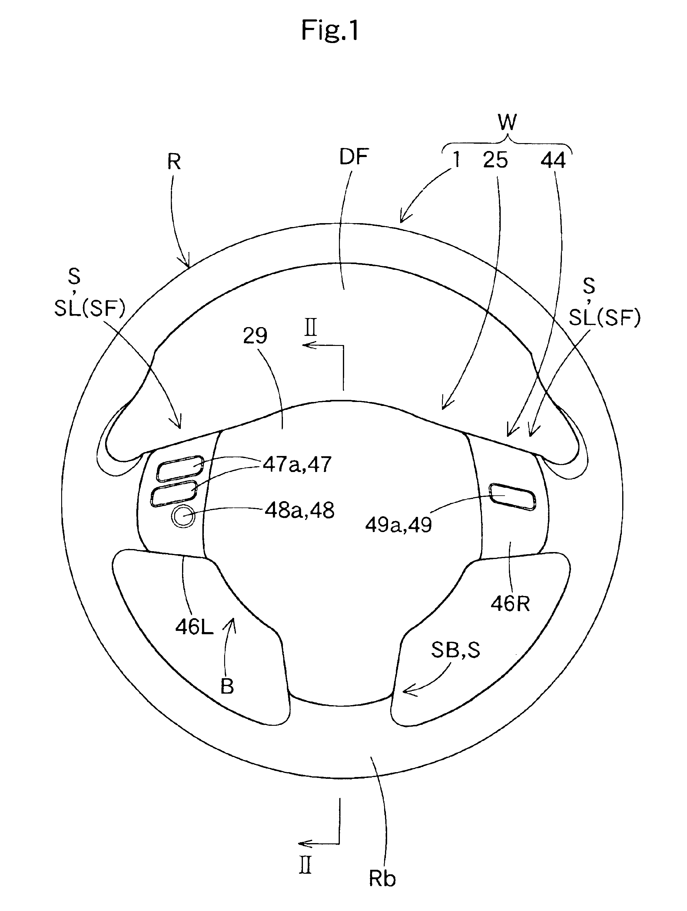
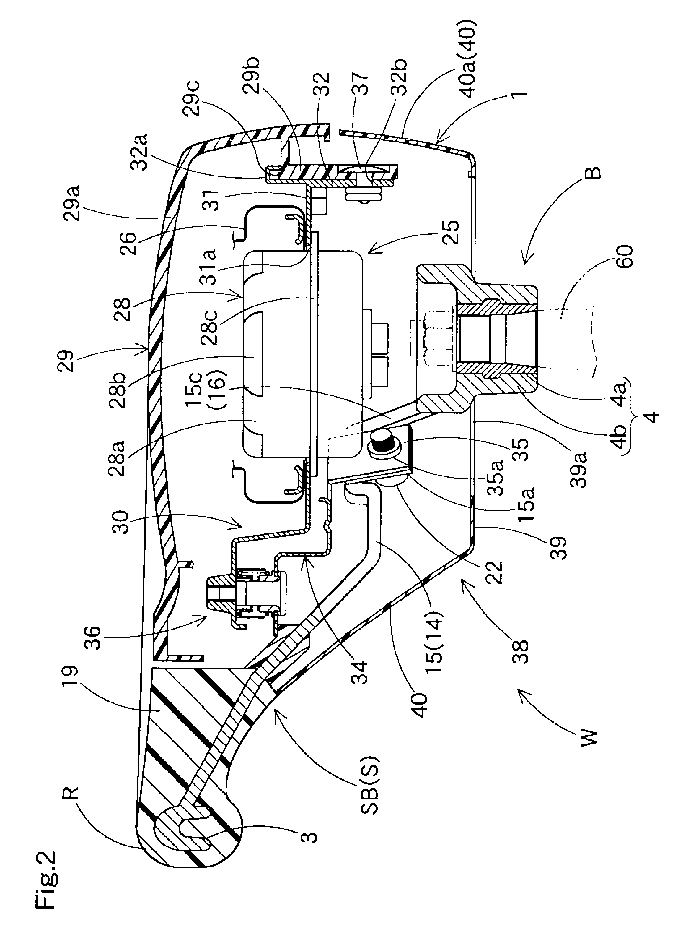
[0042]Referring to FIGS. 1 and 2, a steering wheel W according to the present invention includes an annular ring portion R for holding in steering operation, a boss portion B located in the center of the ring portion R, and a spoke portion S connecting the ring portion R and the boss portion B. As shown in FIG. 1, the spoke portion S includes two front spokes SF (SL and SR) which neighbor a front space DF in the inner side of the ring portion R and are symmetrically arranged relative to the boss portion B, and one rear spoke SB arranged rearward of the front spokes SF. The steering wheel W includes, as components, a steering wheel body 1, an airbag device 25 wh...


PUM


Abstract

Upon self-alignment of a steering wheel, a steering wheel body has its ring plane displaced toward the vertical plane by plastic deformation of the steering wheel core. There is located a switch operation portion in at least one of the two front spokes neighboring a front space inside the ring portion and generally symmetrically arranged relative to the boss portion. The cores of the front spokes are further provided at positions generally symmetric relative to the boss portion and to the boss portion relative to the switch operation portion with deformable portions, respectively, to be twist-deformable upon self-alignment.

Description

[0001]The present application claims priority from Japanese Patent Application of Umemura et al., filed Sep. 4, 2002, under No. 2002-259138, its entirety is hereby incorporated into the present application by this reference.BACKGROUND OF THE INVENTION[0002]1. Field of the Invention[0003]The present invention relates to a vehicle steering wheel capable of displacing a ring plane toward the vertical plane by deforming a steering wheel core plastically upon self-alignment of the steering wheel. Here, self-alignment is a behavior of a steering wheel which deforms a steering wheel core plastically such that the top surface of a ring portion may be proximate to the vertical plane when an impact forward and generally in horizontal direction is applied to the rear part of the ring portion of the steering wheel as mounted on a vehicle. By this behavior, the ring plane hits the driver flatly, thereby the impact against the driver is relieved.[0004]2. Description of Related Art[0005]In the pri...

Claims


Application Information

Patent Timeline
Patent Type & Authority Patents(United States)
IPC IPC(8): B60R21/20B62D1/11B62D1/04B60R21/215B60R21/2165
CPCB60R21/21658B62D1/11B62D1/046Y10T74/20834
Inventor UMEMURA, NORIOSAKURAI, KOJIISOMURA, MOTOI
Owner TOYODA GOSEI CO LTD
Why Eureka
Try Eureka