Fluid spigot and filter unit

a technology of fluid spigot and filter unit, which is applied in the direction of valve housing, filtration separation, separation process, etc., can solve the problem of difficulty in easily accessing the filter cannister

Inactive Publication Date: 2005-09-13
QMP
View PDF7 Cites 20 Cited by
  • Summary
  • Abstract
  • Description
  • Claims
  • Application Information

AI Technical Summary

Problems solved by technology

Since the workspace under a sink can be limited, it can sometimes be difficult to easily access a filter cannister.

Method used


Image

  • Fluid spigot and filter unit
  • Fluid spigot and filter unit
  • Fluid spigot and filter unit

Examples


Embodiment Construction

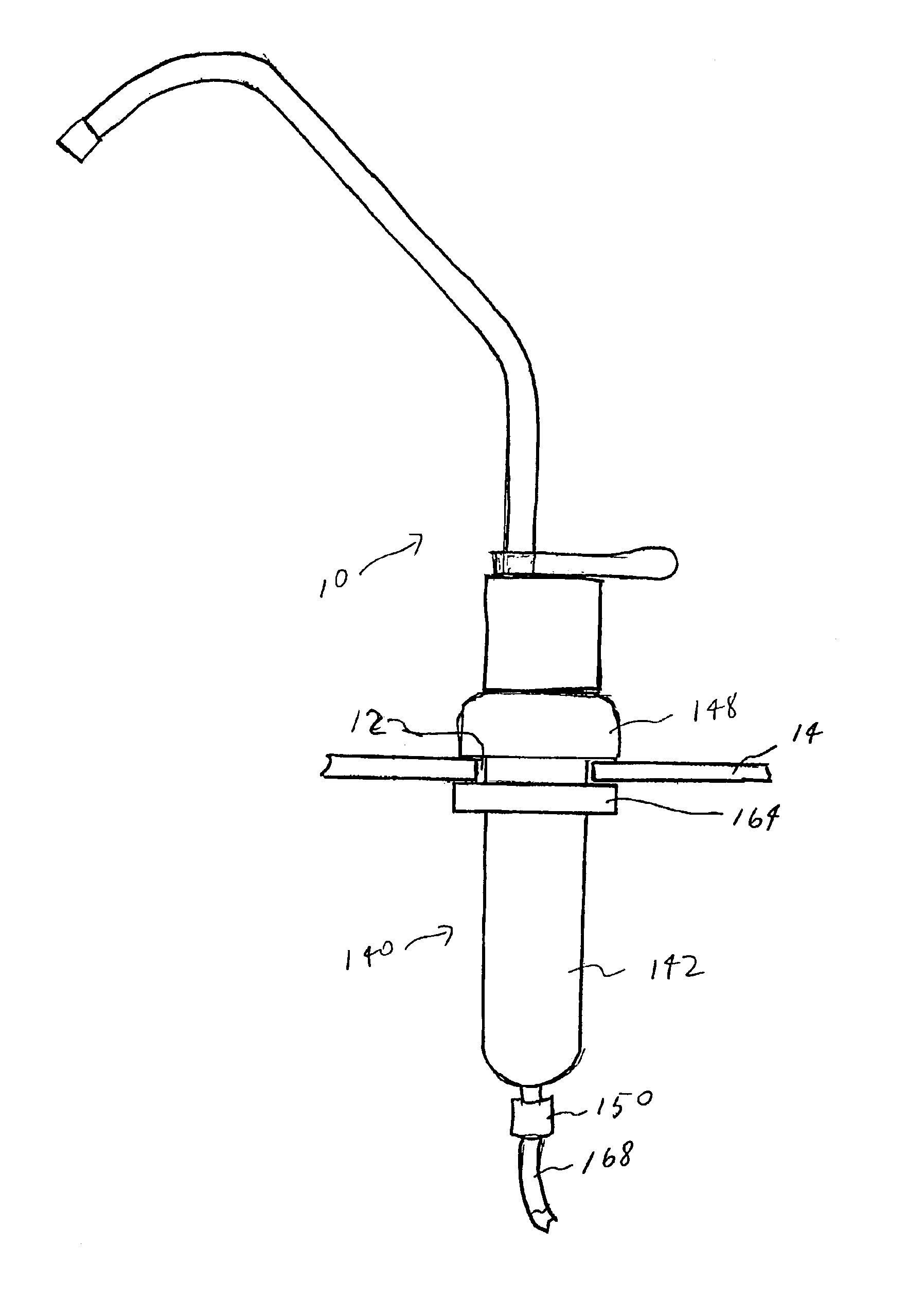
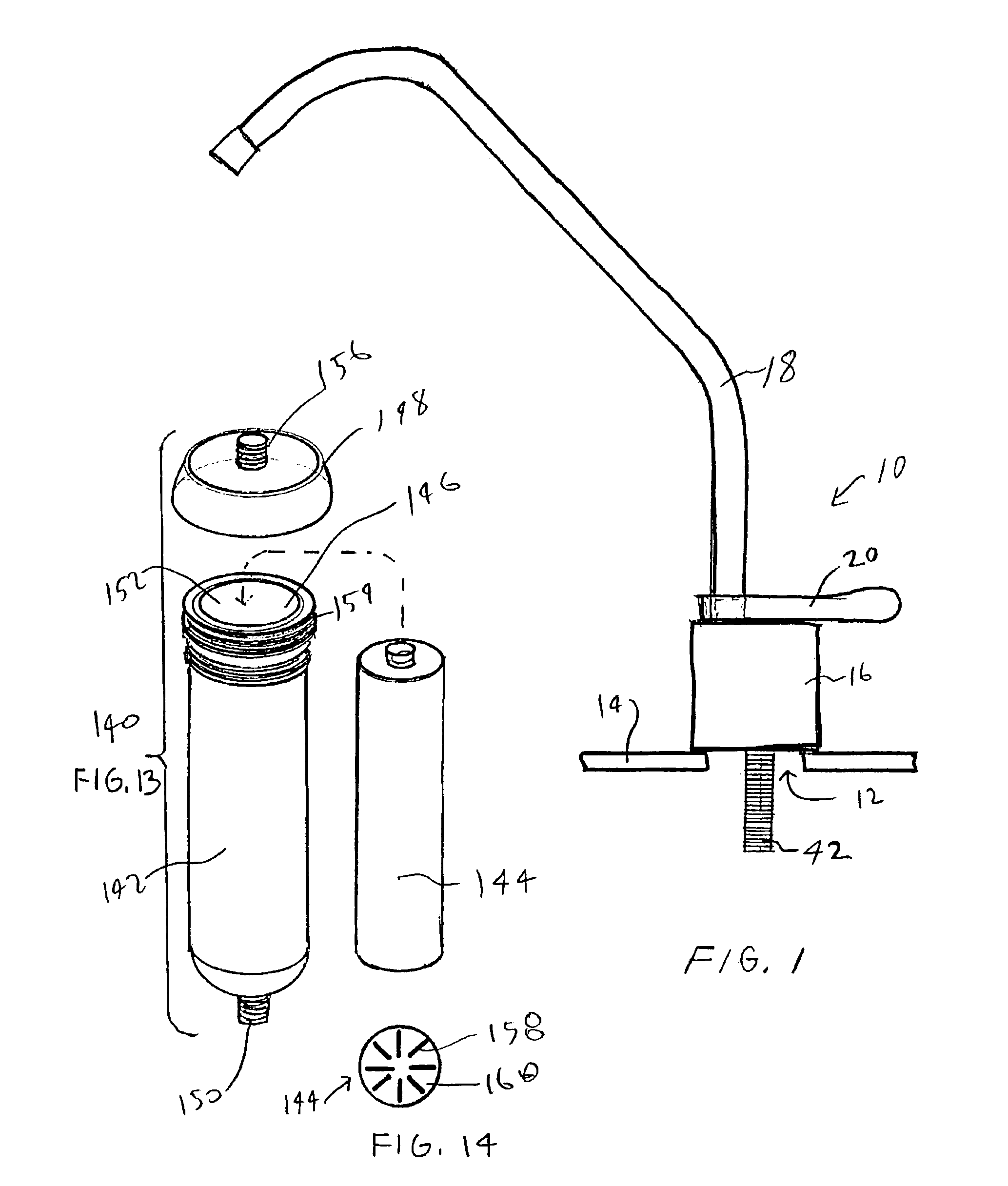
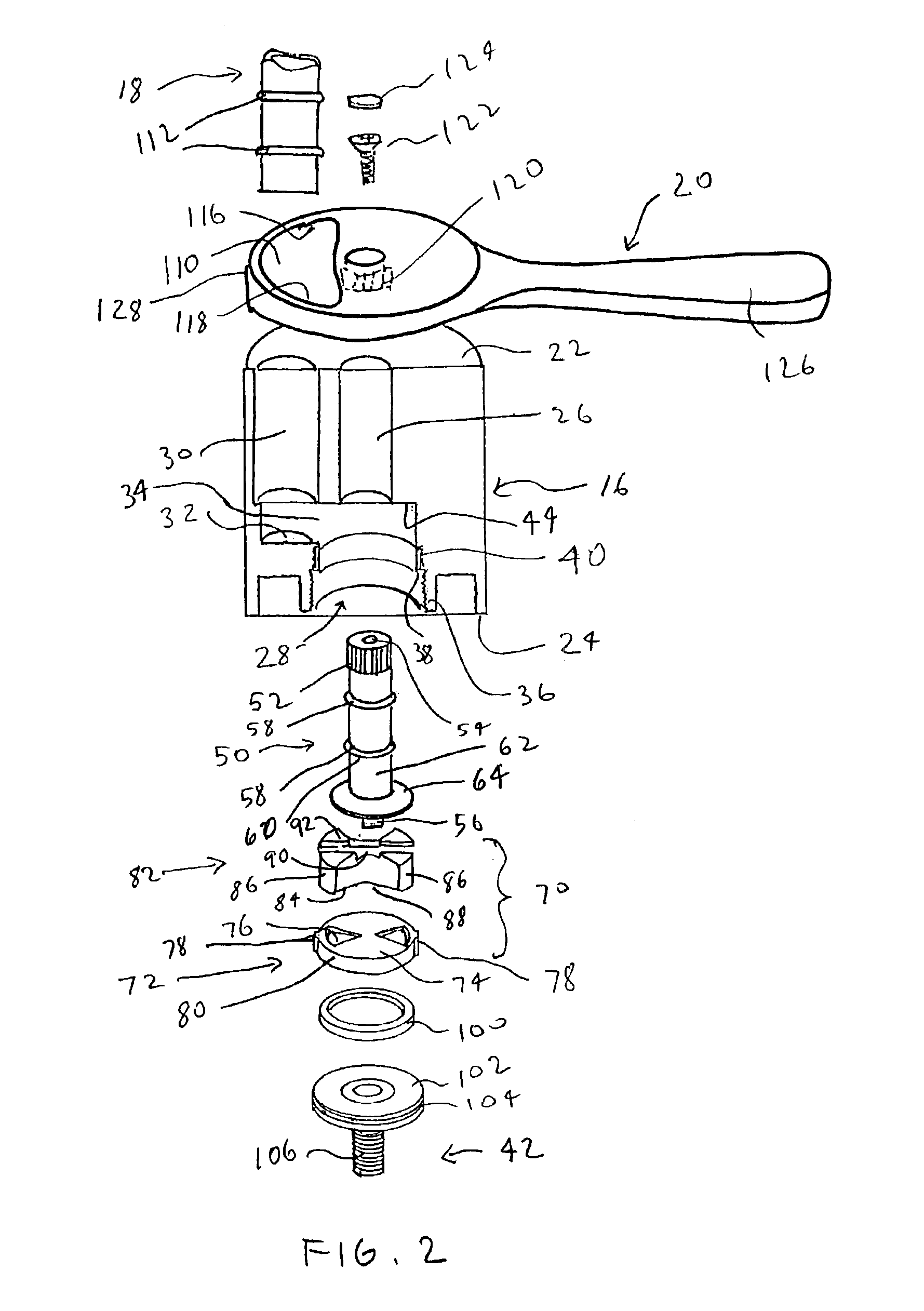
[0046]For the detailed description of the invention turning to FIG. 1, there is shown a side view of an exemplary fluid spigot 10 inserted through an opening 12 in a sink's rim 14, countertop or any other surface to which the fluid spigot 12 is attached. Fluid spigot has a spigot body 16, a spigot tube 18 and a handle 20. Extending from below spigot body 16 is a fluid supply adapter 42. Fluid supply threaded adapter 42 has a threaded shaft portion 106 through which fluid will pass.

[0047]FIG. 2 is a exploded and partially exposed view of the exemplary spigot body 16 of FIG. 1. Spigot body 16 has a top 22 and bottom 24. A valve stem tunnel 26 is formed through a top 22 of spigot body and extends into a valve cavity 28, which extends from bottom 24 of spigot body 16. A fluid outlet tunnel 30 is formed through top 22 of spigot body and extends downwardly to a fluid outlet tunnel end 32. There is an opening 34 formed between fluid outlet tunnel 30 and valve cavity 28 to permit fluid to f...


PUM

PropertyMeasurementUnit
diameteraaaaaaaaaa
perimeteraaaaaaaaaa
friction corrosion resistantaaaaaaaaaa

Abstract

A fluid spigot with a spigot body, a spigot tube, a rotary disc valve located in a valve cavity in the spigot body, the rotary disc valve having an opened and closed positions, a valve stem for turning the rotary disc valve, and a handle for turning the valve stem. The invention further provides a filter unit for attachment to a water spigot or faucet. The filter unit has a filter cannister with a hollow body with a fluid inlet and an open mouth portion, a filter sized to fit within the filter cannister, and an adapter that fits over the open mouth portion of the filter canister, wherein the filter cannister is sized to fit through a hole in a sink rim, the filter being replaceable from above the sink by removing the adapter to access the filter.

Description

BACKGROUND OF THE INVENTION[0001]The invention relates to a new fluid spigot design, and more particularly to a spigot design that utilizes a disc valve design to simplify the construction of the spigot design, as well as a a filter unit that can be used in an in sink rim hole and the like, used in combination with the fluid spigot design or other water spigots and faucets.[0002]With growing concern about water quality, many individuals prefer not to drink tap water unless it is first filtered. There exists a variety of different filtration systems including reverse osmosis systems, activated carbon filtration systems, distillation systems, activated metal particle filtration systems and the like. Some of these systems have a portion that sits on the user's countertop. Some of these systems attach directly to a user's water faucet, and some systems are located undercounter below a sink or outdoors. In the case of undercounter filtration systems which are located below a sink surface...

Claims


Application Information

Patent Timeline
Patent Type & Authority Patents(United States)
IPC IPC(8): B01D35/00B01D35/04C02F1/00E03C1/04F16K3/02F16K27/04F16K3/08
CPCB01D35/04C02F1/003E03C1/04E03C1/0412F16K3/08F16K27/045C02F2307/06E03C2201/40Y10T137/794Y10T137/86743Y10T137/9464
Inventor VIDAL, FREDDY
Owner QMP
Why Eureka
Try Eureka