Occupant protective arrangement and a vehicle therewith

a protective arrangement and occupant technology, applied in the direction of pedestrian/occupant safety arrangement, vehicle components, superstructure subunits, etc., can solve the problems of high stiffness, increased number of parts and weight, and difficulty in providing the engagement part b>14, and achieve the effect of less stiffness

Active Publication Date: 2005-09-13
MITSUBISHI MOTORS CORP
View PDF7 Cites 10 Cited by
  • Summary
  • Abstract
  • Description
  • Claims
  • Application Information

AI Technical Summary

Benefits of technology

[0013]The pillar panel or second side member can be less stiff than the side roof panel or first side member. The pillar trim or third sid

Problems solved by technology

Since the pillar trim 14 is ordinarily made of resin, however, it is difficult to provide the engagement part 14a with a high stiffness.
Therefore, the prior art requires an additional L-shaped plate part to the engagement part 14a, and thus has the problem of increasing the number of parts and the weight.
A

Method used


Image

  • Occupant protective arrangement and a vehicle therewith
  • Occupant protective arrangement and a vehicle therewith
  • Occupant protective arrangement and a vehicle therewith

Examples


Embodiment Construction

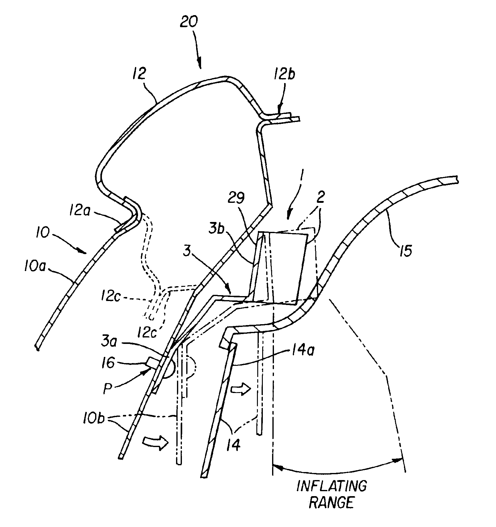
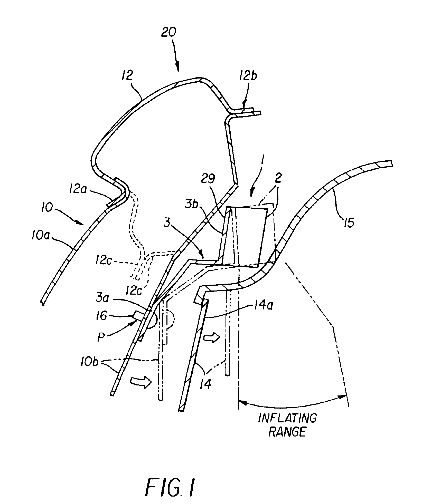
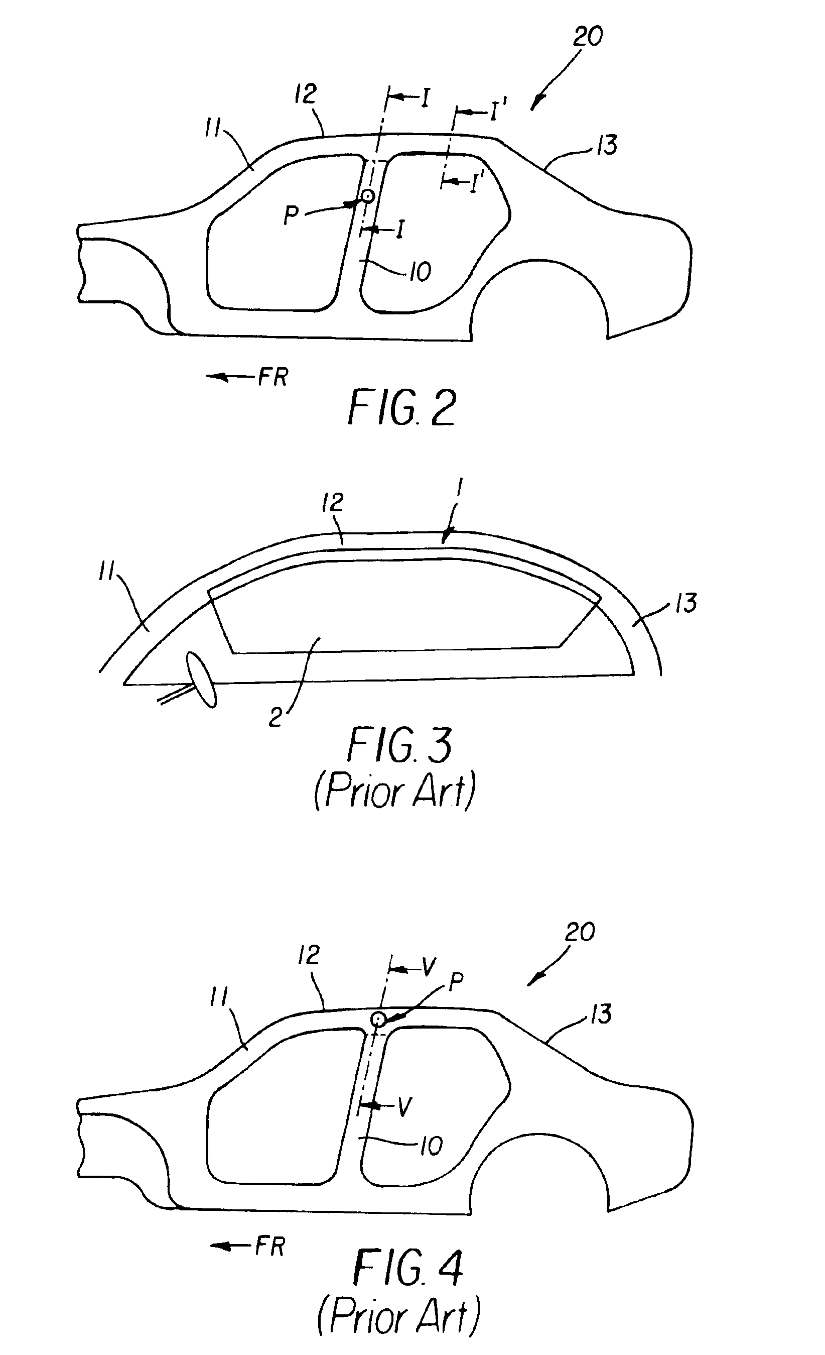
[0024]A detailed description of an embodiment of an occupant protective arrangement for a vehicle according to the present invention follows with reference to the accompanying drawings. FIG. 1 is a schematic sectional view showing the basic components of the occupant protective arrangement according to the embodiment of the present invention, and FIG. 2 is a side view showing a vehicle body to which is applied the occupant protective arrangement shown in FIG. 1. Note that FIG. 1 mainly illustrates a section taken along I—I of FIG. 2, but also partially illustrates a section taken along I′—I′ of FIG. 2 in phantom.

[0025]As shown in FIG. 1, a center pillar 10 is comprised of an outer panel (outer pillar panel) 10a disposed on the outer side of a vehicle and an inner panel (inner pillar panel) 10b disposed on the inner side of the vehicle. The edges (not shown) of the panels 10a and 10b in the longitudinal direction of the vehicle are welded to each other. In the upper part of the cente...


PUM


Abstract

A vehicle has an occupant protective arrangement, which a bracket. The bracket has aholding part that holds an airbag on a pillar panel and a mounting part that is mounted on the pillar panel. The mounting part is located below the lower end of a side roof panel, and the airbag is positioned above the bracket mounting part. With this arrangement, it is possible to inflate the airbag in a reliable manner while preventing the pillar trim and the airbag from interfering with each other.

Description

CROSS-REFERENCE TO THE RELATED APPLICATION[0001]The disclosure of priority Application No.2002-92014 filed in Japan on Mar. 28, 2002, on which a priority is claimed under 35 U.S.C. § 119(a), in its entirety, including the drawings, claims, and the specification thereof, is incorporated herein by reference.BACKGROUND[0002]Driver / passenger-side airbags have been widely used as protective equipment in automobiles for protecting the occupant(s). In addition to front airbags, an airbag deployed on the side of a vehicle compartment are also being used. For example, a so-called curtain deployed to extend between a front pillar 11 and a rear pillar 13, as shown in FIG. 3, and a so-called side airbag provided on the side of a vehicle compartment have been developed and put into practical use.[0003]Such a curtain airbag (hereinafter simply referred to as “airbag ”) 1 is comprised of an airbag main body 2 stored in the vicinity of a side roof rail (or a side roof panel) 12, along the longitudi...

Claims


Application Information

Patent Timeline
IPC IPC(8): B60R21/16B60R21/20B60R13/02B60R21/213
CPCB60R13/02B60R21/232B60R21/213B60R21/21B62D25/06
Inventor YAMAMURA, DAISUKENAGAYAMA, NORITAKA
Owner MITSUBISHI MOTORS CORP
Why Eureka
Try Eureka