Insertion facilitation device for catheters

Inactive Publication Date: 2011-03-17
INGENION
View PDF23 Cites 17 Cited by
  • Summary
  • Abstract
  • Description
  • Claims
  • Application Information

AI Technical Summary

Benefits of technology

[0013]Use of an insertion facilitation device according to some embodiments of the invention enables selection of a smaller, less stiff, softer and/or otherwise more desirable tube-like structure, e.g. a catheter, for use in a passage. For example, a smaller, more flexible and/or softer catheter which would present insertion difficulties if insertable at all without an insertion facilitation device may otherwise be used with an insertion facilitation device according to various embodiments of the invention so as to increase the comfort of a patient, for example where the catheter will remain in place for a period of time.
[0014]According to some embodiments of the invention, an insertion facilitation device releasably engages with a tube-like structure and provides stiffness or greater stiffness to the tube-like structure. In some embodiments, the releasable engagement substantially reduces or eliminates the risk of the insertion facilitation device dislodging or separating from the tube-like structure at least during insertion thereof in a passage. (“Engage” and formatives thereof as used herein are meant in a broad sense and encompass sufficient holding or retaining, etc., for the purposes described herein, and encompass various forms of attachment, fixation, securement, bonding, integral formation, etc. “Releasably engage” and formatives thereof as used herein are meant in a broad sense and encompass forms of engagement that can be disengaged as disclosed herein. For example, not every form of engagement is also a releasable engagement.) For example, a prior art urinary catheter known as a Foley catheter includes eyelets in the proximal end portion. (For ease of description, the leading end or portion of a tube-like structure, insertion facilitation device or stiffener (discussed below) relative to a passage will be referred to herein as the proximal end or portion, and the trailing end or portion will be referred herein as the distal end or portion.) Use in a Foley-type catheter of an insertion facilitation device according to various embodiments of the invention in which the proximal portion of the device is engaged with the catheter essentially eliminates the risk that the proximal end portion

Problems solved by technology

However, the stiffness of the tube-like structure is great

Method used


Image

  • Insertion facilitation device for catheters
  • Insertion facilitation device for catheters
  • Insertion facilitation device for catheters

Examples


Embodiment Construction

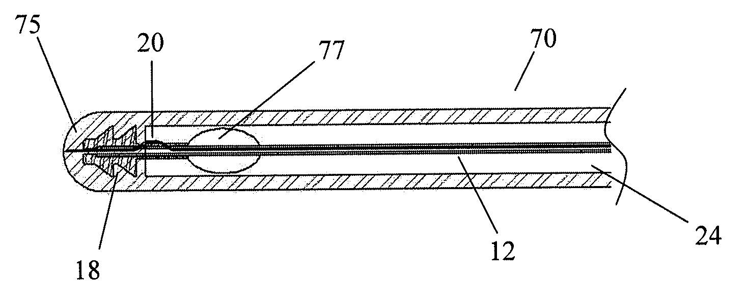
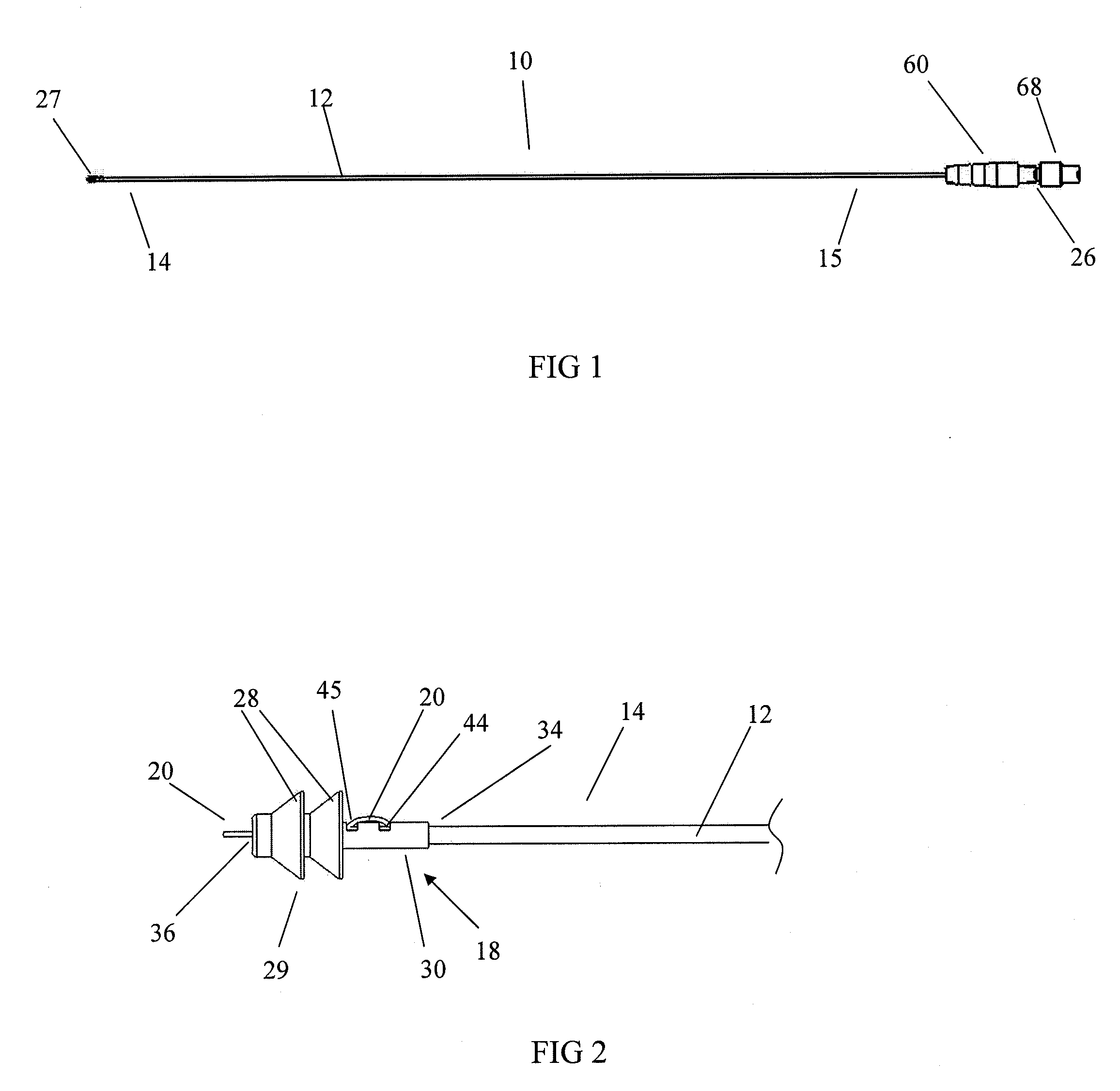
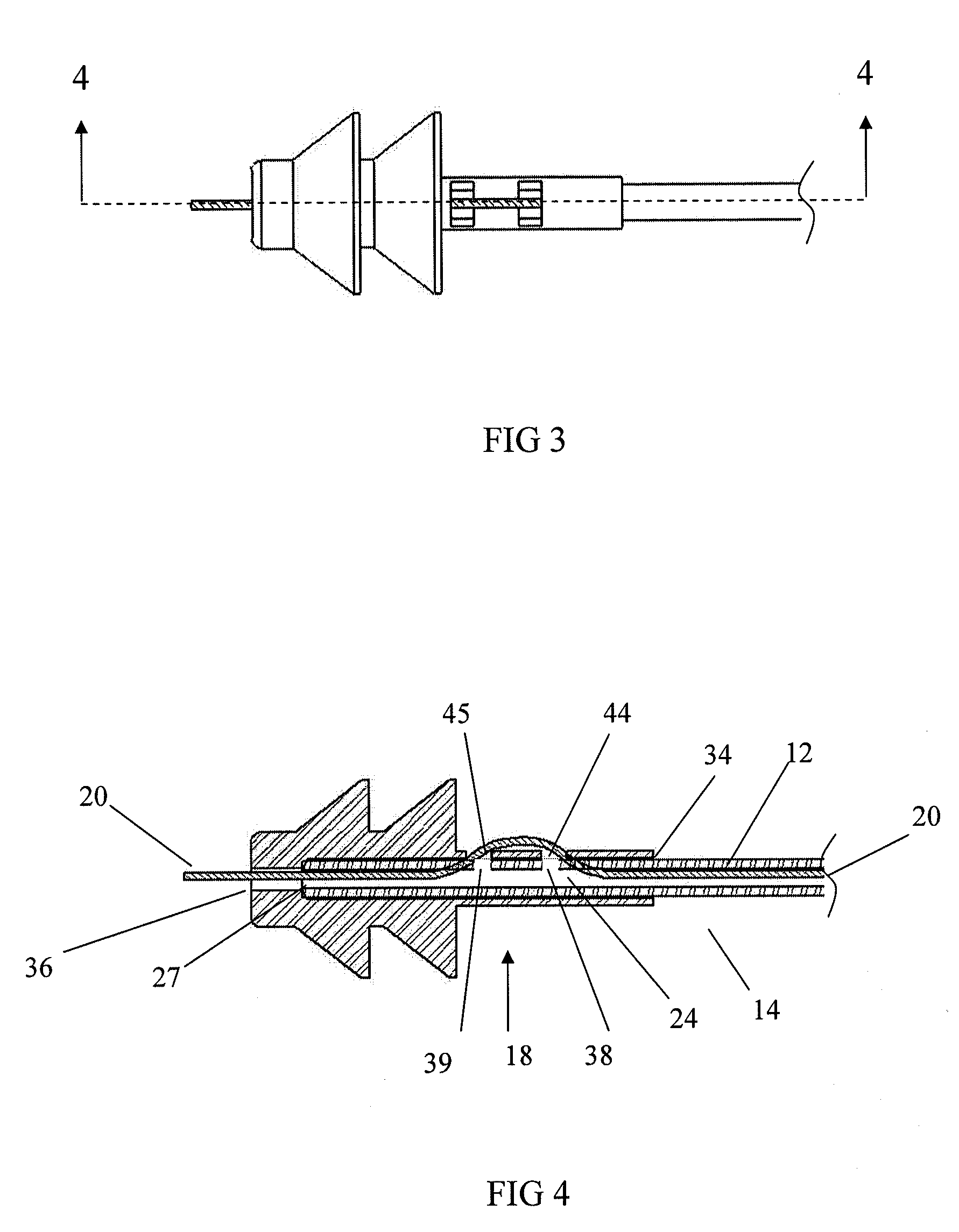
[0101]Embodiments of the invention are described below with reference to the accompanying drawings which depict embodiments of insertion facilitation devices and catheters. However, it is to be understood that application of the invention encompasses other tube-like structures and is not limited to catheters, and to insertion facilitation devices other than those illustrated. Also, the invention is not limited to the depicted embodiments and the details thereof, which are provided for purposes of illustration and not limitation.

[0102]Insertion facilitation devices (or tools) according to embodiments of the invention provide stiffness to a tube-like structure, as discussed above, and a range of stiffnesses can be provided. As discussed above, such stiffness can facilitate insertion of a tube-like structure into a passage. However, it should be understood that the particular stiffness which the device is to provide may depend upon, e.g., the particular application, tube-like structure...


PUM


Abstract

Devices that facilitate insertion of tube-like structures, e.g., catheters and other medical devices, into passages in mammalian bodies, e.g. in the human body. Devices according to various embodiments of the invention provide greater stiffness and/or rigidity to elongated tube-like structures. According to some embodiments, a portion or the entire insertion facilitation device can be removed from the tube-like structure after insertion thereof. According to some embodiments of the invention, an insertion facilitation device comprises a releasable engagement arrangement to releasably engage the stiffener and a tube-like structure to inhibit or prevent relative motion between the stiffener and tube-like structure.

Description

CROSS REFERENCE TO RELATED APPLICATIONS[0001]This application claims priority to U.S. Patent Application Ser. No. 61 / 242,138 filed Sep. 14, 2009 entitled “Insertion Facilitation Device for Catheters,” the disclosure of which is incorporated herein by reference.BACKGROUND OF THE INVENTION[0002]The invention disclosed herein relates to devices that facilitate insertion of tube-like structures, e.g., catheters and other medical devices, into passages, e.g., in the human or other mammalian body. The invention has application or potential application to many medical fields, including urology, vascular, thoracic, cardiology, gastroenterology and proctology.[0003]Tube-like structures such as catheters, for example, and other devices are inserted into body passages, e.g. of humans, for a variety of purposes. Some currently used tube-like structures, because of material selection, size, shape, or other consideration, lack sufficient stiffness to support the weight of the structure without de...

Claims


Application Information

Patent Timeline
IPC IPC(8): A61M25/00
CPCA61M25/0068A61M2025/09125A61M2025/0063A61M25/0102
Inventor WINEGAR, THOMAS W.
Owner INGENION
Why Eureka
Try Eureka