Multiple vertical auger cutter mixer

Inactive Publication Date: 2005-09-20
NEW DIRECTION EQUIP
View PDF10 Cites 41 Cited by
  • Summary
  • Abstract
  • Description
  • Claims
  • Application Information

AI Technical Summary

Problems solved by technology

Large mixers with two or three vertical spindles also discharge the material rapidly but tend to leave some fodder on the tub floor.

Method used


Image

  • Multiple vertical auger cutter mixer
  • Multiple vertical auger cutter mixer
  • Multiple vertical auger cutter mixer

Examples


Embodiment Construction

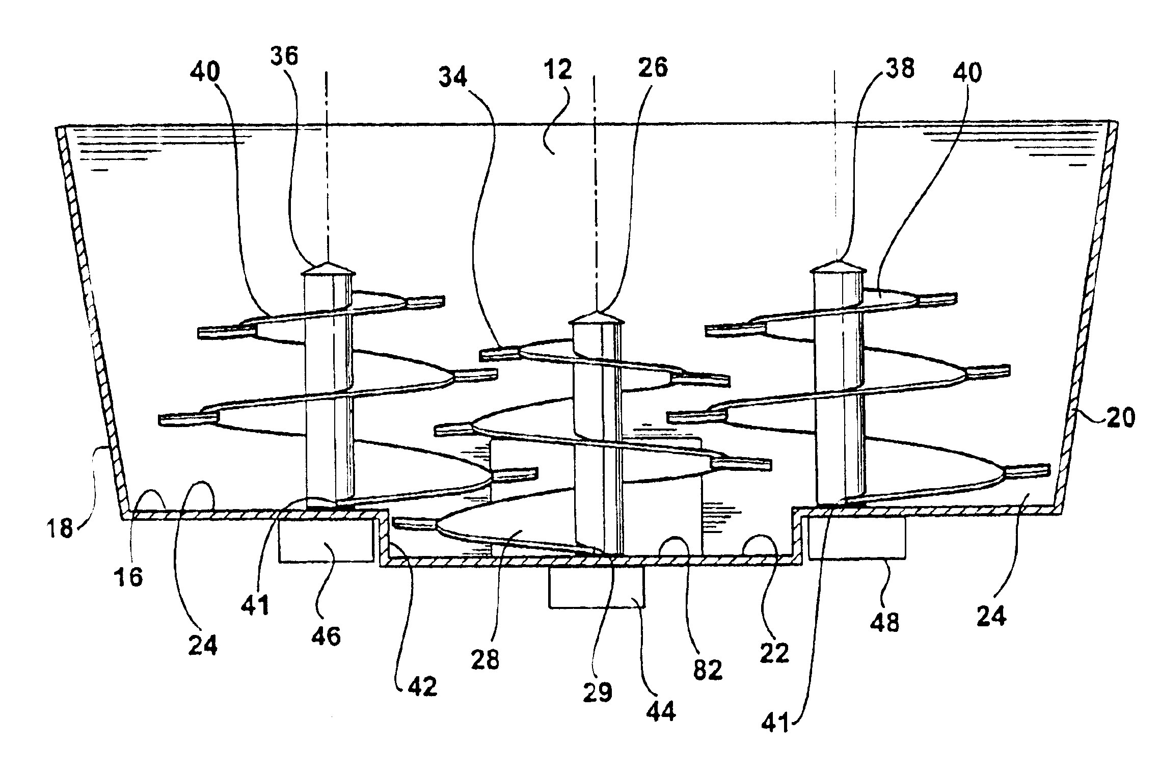
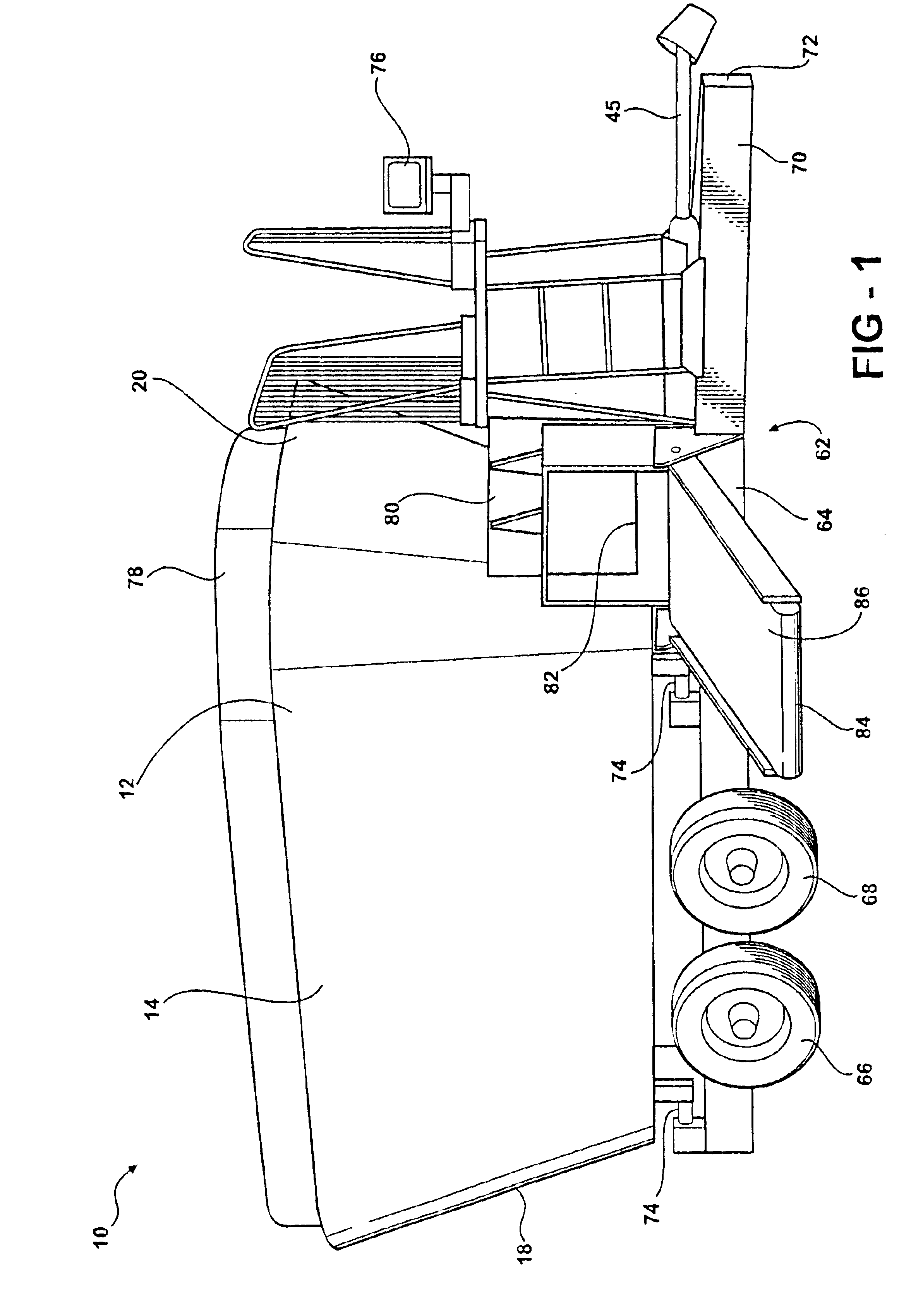
[0014]The multiple vertical auger cutter mixer 10 includes a tub 12 with walls 14 and a floor 16. The walls 14 surround the tub 12 and extend upward and outward from the floor 16. The ends 18 and 20 of the tub 12 are accurate as viewed from above.

[0015]The floor 16 of the tub 12 includes a primary floor 22 that forms the lower portion of the tub. A secondary floor 24 is raised up above the primary floor 22. The secondary floor 24 can have a single section, two sections as shown in FIG. 2, or more sections.

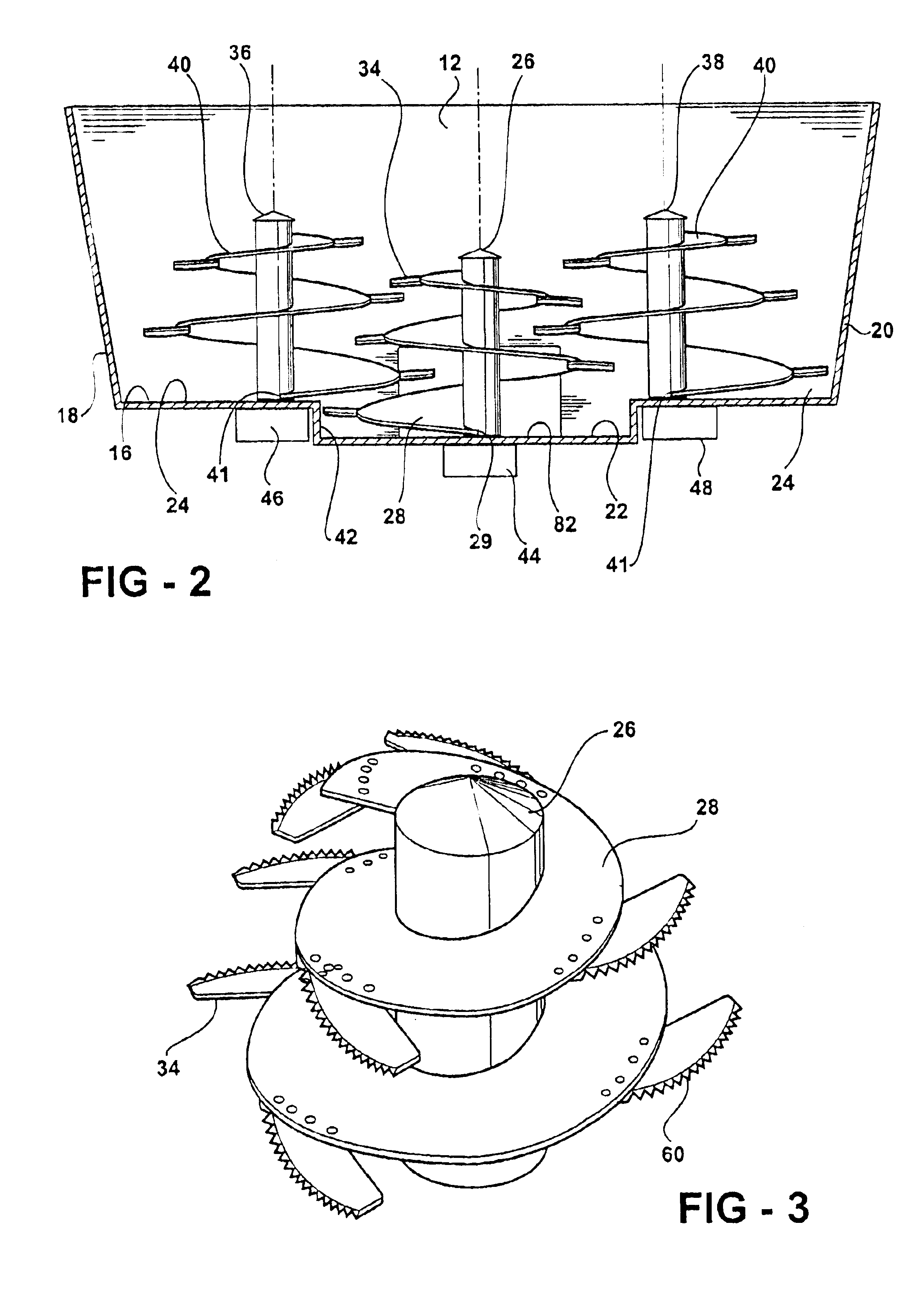
[0016]A primary vertical spindle 26 is journaled on the primary floor 22. The primary spindle 26 has auger flighting 28 that extends radially outward from the spindle. The radially outer edge of the flighting 28 extends radially out co sweep an envelope that defines a conical area. The flighting 28 at the bottom of primary spindle extends radially outward from the spindle at least twice as far as the flighting at the top of the spindle. Cutters 34 are clamped to the radially outer ...


PUM


Abstract

The cutter mixer has a mixer tub with side walls and a floor. The floor includes a primary floor portion at a lower elevation. At least one secondary floor is positioned vertically above the primary floor portion. A primary vertical spindle is journaled in the center of the primary floor. A secondary vertical spindle is journaled on the secondary floor. Auger flighting is attached to the primary spindle. Auger flighting is also attached to the secondary spindle. The flighting decreases in width from the bottom to the top of each spindle. The bottom of the flighting on the primary spindle sweeps over substantially all the primary floor. The flighting on the secondary spindle overlaps the flighting on the primary spindle and sweeps fodder from the secondary floor to the primary floor. The augers are driven to cut and mix fodder and discharge fodder from the primary floor.

Description

[0001]The disclosure incorporates a multiple vertical auger cutter mixer disclosed in provisional patent application 60 / 379,988, filed May 13, 2002, whose priority is claimed for this application.TECHNICAL FIELD[0002]The cutter mixer for cutting and mixing rations for cattle and other animals has multiple augers that rotate about vertical axes.BACKGROUND OF THE INVENTION[0003]Cattle are fed rations that include fodder, silage, and protein supplements. The fodder includes grasses and other plants such as clover and alfalfa. Silage is various green plants that are chopped into small pieces and fermented in a silo. The protein supplement is usually ground or palletized grain. Grains that are commonly used include corn, milo, soy beans, barley and oats. Alfalfa can be processed and used as a protein supplement. Fish meal has also been used as a protein supplement in the past.[0004]The fodder is dried and baled in most cases. The bales are generally large round bales or large rectangular...

Claims


Application Information

Patent Timeline
Patent Type & Authority Patents(United States)
IPC IPC(8): B02B5/00B02B5/02B02C9/00B02C9/04B03B7/00B02C19/00A01K5/00B01F7/24B01F13/10
CPCA01K5/004B01F7/241B01F13/1044B01F2013/108Y10S241/605B01F27/922B01F33/8305B01F33/83611
Inventor DOUGLAS, SCOTT F.
Owner NEW DIRECTION EQUIP
Why Eureka
Try Eureka