Tooth inclination assessment

Inactive Publication Date: 2005-09-20
WALES COLLEGE OF MEDICINE UNIV OF +1
View PDF2 Cites 9 Cited by
  • Summary
  • Abstract
  • Description
  • Claims
  • Application Information

AI Technical Summary

Benefits of technology

[0003]It is an aim of this invention to provide a valid, reliable, simple, inex

Problems solved by technology

However, lateral cephalometric radiograph derived axial inclinations of incisors are prone to

Method used


Image

  • Tooth inclination assessment
  • Tooth inclination assessment
  • Tooth inclination assessment

Examples


Embodiment Construction

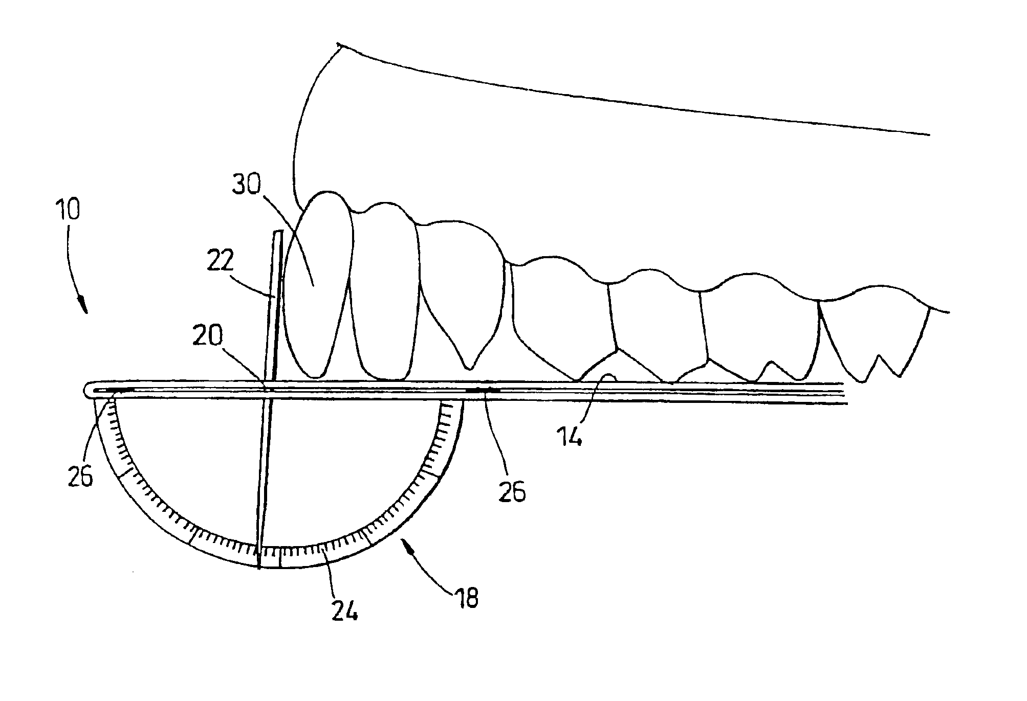
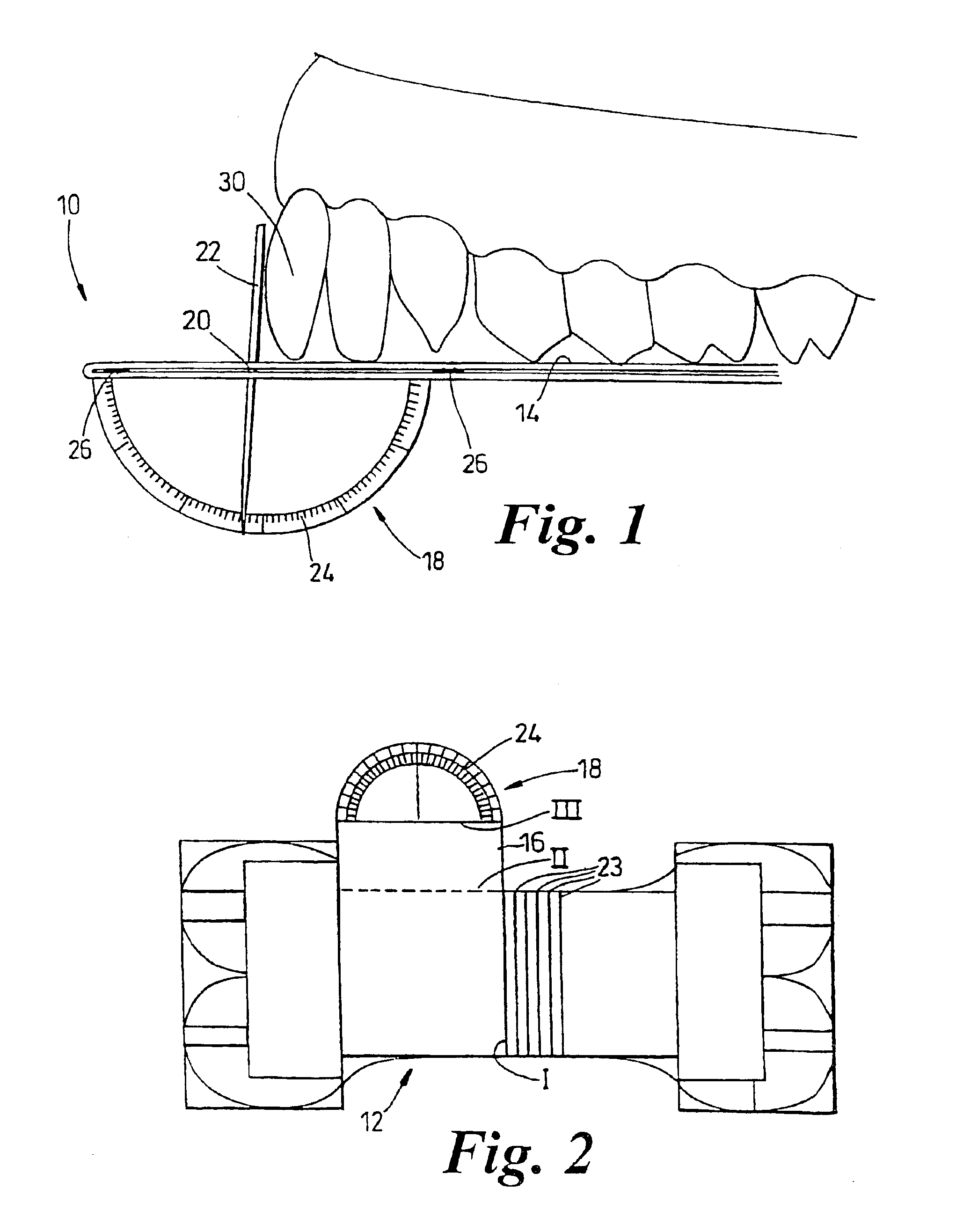
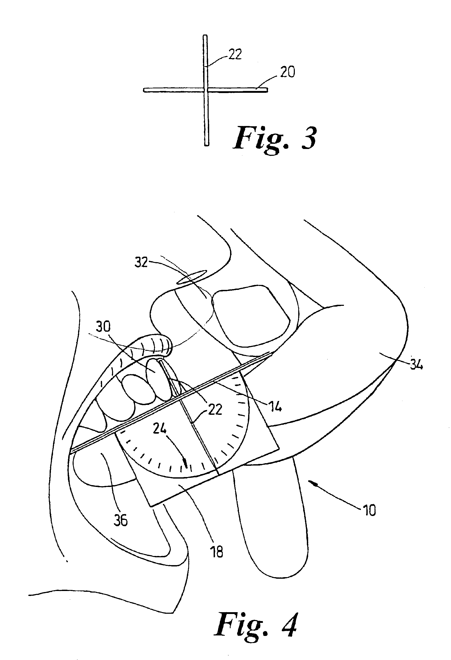
[0024]Referring to the Figures, the tooth inclination protractor 10 comprises a blank 12 of suitable card or plastic sheet folded double about fold line I to provide a flat datum surface 14. From one side of the blank 12 projects a tab 16 which terminates in a graduated semicircular protractor portion 18. Rotatably secured at the origin of the protractor portion 18 is the shaft 20 of an indicator pin 22. One half of the pin projects below the datum surface as viewed in FIG. 1 to terminate at the scale 24 of the protractor portion 18, whilst the other half of the pin projects upwardly to be pivoted into contact with the labial surface of the incisor tooth whose surface of inclination is to be measured.

[0025]The blank 12 may be provided with adhesive regions 26 on the meeting surfaces which define the datum surface 14, with an interruption to receive the shaft 20 of the indicator pin. Likewise the meeting surfaces of the datum surface and the tab 16 may carry adhesive regions.

[0026]Fo...


PUM


Abstract

A tooth inclination apparatus for allowing assessment of the angle of inclination of an incisor tooth or cast thereof includes a plane element providing a flat datum surface for resting against e.g. the upper molars in the maxillary plane. From the underside of the plane element projects a protractor portion with a graduated angular scale which measures the angular deviation of an indicator pin pivoted to the plane member and moved to contact the tooth whose inclination is being measured. Other mechanical or electro-optic devices may be used to determine the inclination of the incisor relative to the datum surface.

Description

BACKGROUND OF THE INVENTION[0001]This invention relates to the assessment of the inclination of the left, right, upper or lower incisors relative to a reference such as the maxillary plane or the mandibular plane respectively, or the occlusal plane.[0002]The evaluation of maxillary and mandibular incisor inclinations is an important aspect of orthodontic treatment planning, assessing treatment progress, as well as determining treatment outcome. Incisor inclination has traditionally been assessed by lateral cephalometric radiographic analysis. However, lateral cephalometric radiograph derived axial inclinations of incisors are prone to large digitised errors. In addition, radiographs may cause a small but significant mitotic risk.SUMMARY OF THE INVENTION[0003]It is an aim of this invention to provide a valid, reliable, simple, inexpensive and non-invasive method and apparatus for recording incisor inclination.[0004]According to one aspect, this invention provides a tooth inclination ...

Claims


Application Information

Patent Timeline
IPC IPC(8): A61C19/04
CPCA61C19/04
Inventor RICHMOND, STEPHEN
Owner WALES COLLEGE OF MEDICINE UNIV OF
Why Eureka
Try Eureka