A wireless, remotely controlled, device selection system and method

A technology of remote control equipment and wireless remote control, which is applied in transmission systems, signal transmission systems, lighting devices, etc., to achieve the effects of reducing risks, reducing signal traffic, and improving signal-to-noise ratio

Inactive Publication Date: 2011-05-11
KONINK PHILIPS ELECTRONICS NV
View PDF8 Cites 23 Cited by
  • Summary
  • Abstract
  • Description
  • Claims
  • Application Information

AI Technical Summary

Problems solved by technology

However, the risk of using a remote control device is to accidentally select a different device (such as a light source) than the desired device

Method used


Image

  • A wireless, remotely controlled, device selection system and method
  • A wireless, remotely controlled, device selection system and method
  • A wireless, remotely controlled, device selection system and method

Examples


Embodiment Construction

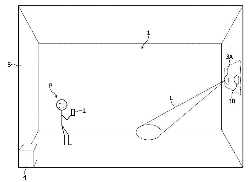
[0047] figure 1 is a schematic diagram of a wireless remote device selection system 1 (that is, a system for wirelessly selecting devices by means of a remote device in structure S), which includes a remote device 2 and a first device 3A and a second device 3B. Assuming that the first device 3A and the second device 3B are light sources or luminaires, alternative devices such as eg awnings, switches or doors may also be represented.

[0048] The remote control device 2 can be a single handheld device or a combination of a handheld device and a central controller 4 .

[0049] A person P can control the operation of the light sources 3A, 3B by using the remote control device 2 . The control involves, for example, turning on / off the light sources, controlling the brightness or color of the light L emitted by the light sources 3A, 3B, and / or controlling the direction in which the light L is emitted from the light sources 3A, 3B.

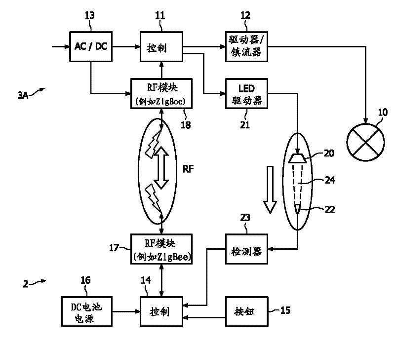
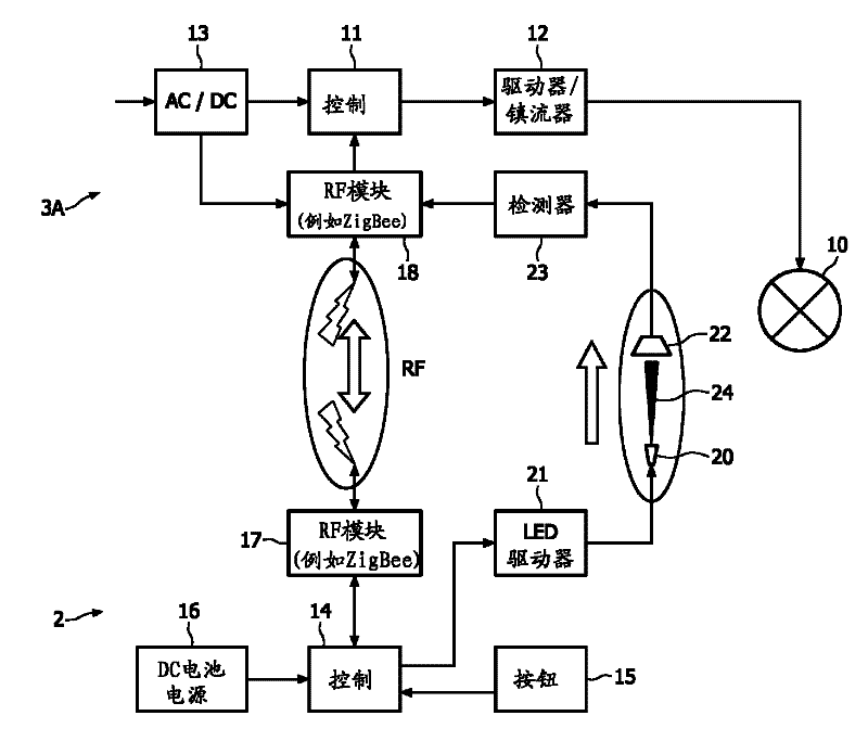
[0050] figure 2 with image 3 Schematic diag...


PUM


Abstract

The invention relates to a wireless remote controlled device selection system for selecting devices. Signal processing provides information for a remote control device. This information is indicative of the angle between the remote control device and the various devices from which a device should be selected. By comparing the angular deviations, the desired device can be selected.

Description

technical field [0001] The invention relates to the field of selecting one or more devices from a plurality of devices, such as lights, by means of a wireless remote control device. Background technique [0002] In current lighting systems comprising multiple light sources, selection and control of the light sources is typically done through fixed equipment such as wall panels with switches. A switch is used to control a light source, for example to turn a light on or off, or to dim a light. If the user wants to change any lights, the user must go back to the wall panel. Of course, the user needs to know which switch controls which light source. However, often the user does not have this information because the switch or light source is not marked. This situation is especially problematic in the case of multiple light sources and multiple switches, where the switch controlling the desired light source is found by trial and error. [0003] Remote control devices have rece...

Claims


Application Information

Patent Timeline
Patent Type & Authority Applications(China)
IPC IPC(8): H05B37/02G08C17/02H04B1/20G06F3/033
CPCG08C17/02G08C2201/71H05B47/19H05B47/195
Inventor J.C.塔尔斯特拉P.A.E.约基姆斯L.费里H.T.G.M.彭宁德夫里斯T.C.W.申克
Owner KONINK PHILIPS ELECTRONICS NV
Why Eureka
Try Eureka