Apparatus and method for monitoring electrical cable chafing via optical waveguides

a technology of optical waveguides and optical waveguides, which is applied in the direction of cables, insulated conductors, instruments, etc., can solve the problems of increasing the complexity of making the proper connection, the difficulty of removing and installing electrical cables from objects, and the impracticality of devices

Active Publication Date: 2005-09-27
THE BOEING CO
View PDF6 Cites 12 Cited by
  • Summary
  • Abstract
  • Description
  • Claims
  • Application Information

AI Technical Summary

Benefits of technology

[0006]The present invention makes it practical to utilize optical waveguides to detect chafing of electrical cables. In general, optical waveguides, such as fiber optic strands or fiber optic ribbon, can be utilized to detect chafing of an electrical cable by disposing one or more of such optical waveguides about the periphery of an electrical cable such that any chafing that causes damage to the electrical cable will likely also cause damage to at least one of the optical waveguides. By monitoring such optical waveguides for damage using known techniques, such as optical time domain reflectivity, the existence and location of any such damage can easily be detected, without the need to visually inspect the electrical cable.
[0009]However, utilizing the present invention, multiple optical waveguides associated with one electrical cable segment can be operatively connected to multiple optical waveguides associated with another adjacent electrical cable segment via just one single-pin connector assembly. Thus, the present invention greatly simplifies the configuration and practicality of optical chafe-detection devices.

Problems solved by technology

Unfortunately, the use of large or numerous optical waveguide connectors in connection with optical chafe-detection devices may render such devices impractical in various situations.
Notably, the installation and removal of and electrical cable from an object becomes more difficult as the size and number of connectors that must be fed along the routing path of the cable increases.
Additionally, as the number of connectors required to remove or install an electrical cable increases, so too does the complexity of making the proper connections and time required for the task.

Method used


Image

  • Apparatus and method for monitoring electrical cable chafing via optical waveguides
  • Apparatus and method for monitoring electrical cable chafing via optical waveguides
  • Apparatus and method for monitoring electrical cable chafing via optical waveguides

Examples


Embodiment Construction

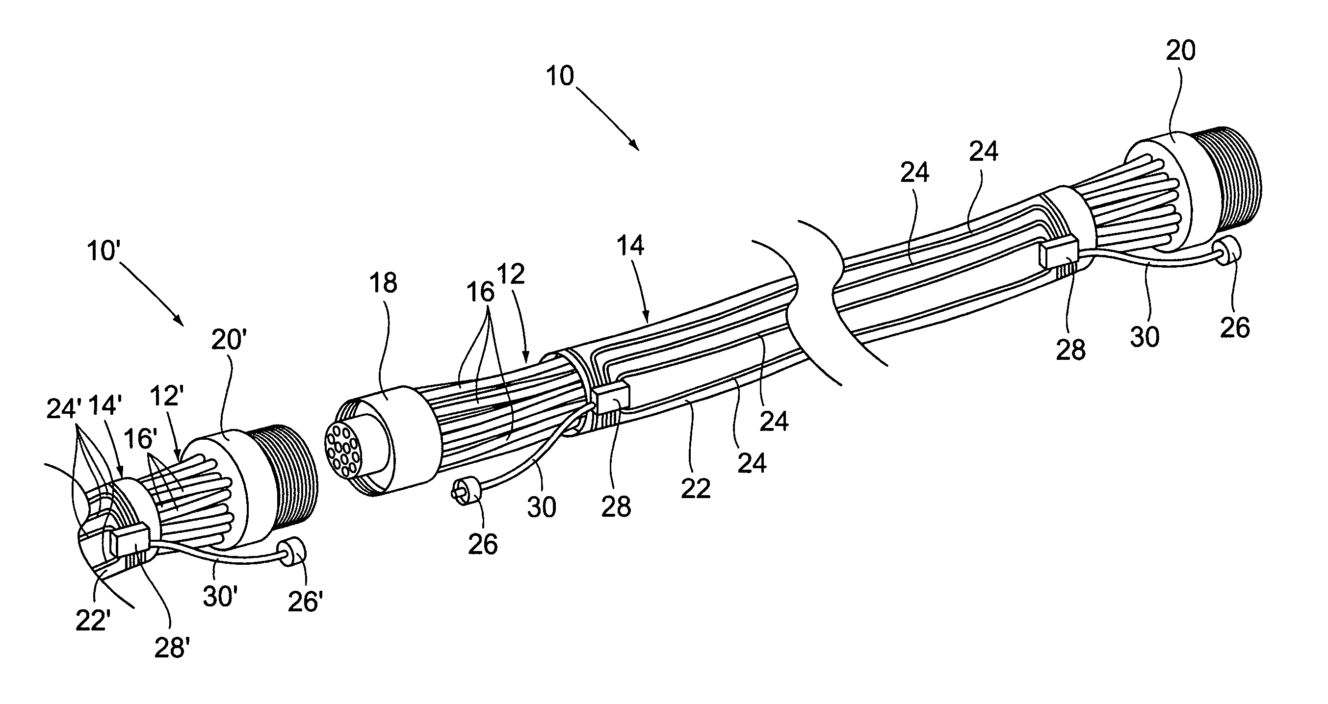
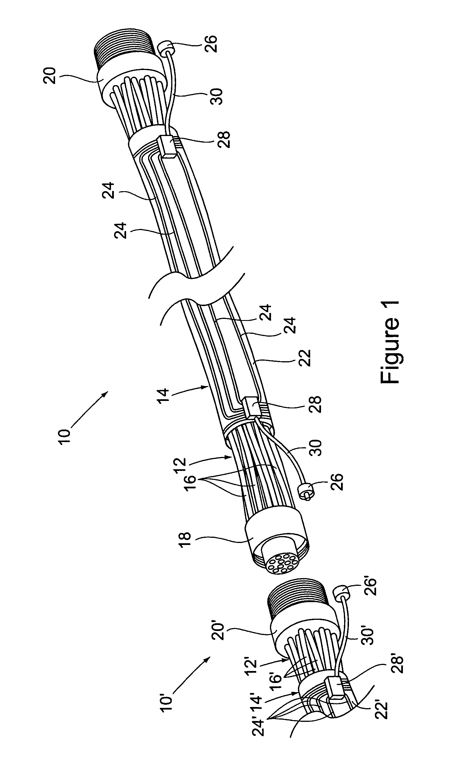
[0017]A first preferred embodiment of an apparatus in accordance with the invention is shown in FIG. 1. Referring to FIG. 1, in this embodiment, a cable 10 preferably comprises an electrical cable segment 12, and a sheath 14.

[0018]The electrical cable 12 could be merely a single electrically conductive wire of any type and form. However, for purposes of describing the invention, the electrical cable 12 is presumed to comprise a plurality of electrically conductive wires 16 that each extend longitudinally along a trajectory path from a female electrical connector 18 to a male electrical connector 20. The electrical connectors 18, 20 are preferably standard electrical connector fittings and need not necessarily be a matching pair of connectors. In other words, the electrical connectors 18, 20 could be sized differently to attach to particular connectors but not to each other, and could both be male or female.

[0019]The sheath 14 preferably comprises a tubular member 22, a plurality of ...


PUM

PropertyMeasurementUnit
electrically conductiveaaaaaaaaaa
trajectoryaaaaaaaaaa
wavelengthaaaaaaaaaa

Abstract

A method and apparatus for using optical waveguides to detect chafing of electrical cables. Chafing damage is preferably detected by disposing several optical waveguides about the periphery of an electrical cable such that any chafing that causes damage to the electrical cable will likely also cause damage to at least one of the optical waveguides. The disclosed apparatus and method allows multiple optical waveguides of one cable segment to be connected to multiple optical waveguides of an adjacent cable segment using only a single optical waveguide connection, while still allowing each of the optical waveguides of either cable segment to be monitored independently of each other.

Description

BACKGROUND OF THE INVENTION[0001](1) Field of the Invention[0002]This invention pertains to the use of optical waveguides in detecting chafing of electrical cables. In particular, this invention pertains to apparatus and methods for reducing the size and / or number of optical connectors utilized in connection with optical chafe-detection devices, without sacrificing the performance or reliability of such devices.[0003](2) Background[0004]Electrical cables that are subjected to vibrations or other movements are often susceptible to chafing damage. Such chafing damage can expose or sever the electrical wires of such cables, resulting in electrical shorts, arcing, and loss of functionality. When such damage is caused to critical electrical cables, such as those utilized in flight control systems of aircraft, catastrophic consequences, including loss of aircraft and life, can result.[0005]As should be appreciated, identifying the existence of chafing damage before such damage has a serio...

Claims


Application Information

Patent Timeline
Patent Type & Authority Patents(United States)
IPC IPC(8): G01N21/00G01R31/02G02B6/00G02B6/02G02B6/44H04B3/46H01B7/32H01B9/00
CPCG01R31/021G02B6/4469H01B7/32G01R31/008H01B9/005G01R31/58
Inventor WEAVER, THOMAS L.
Owner THE BOEING CO
Why Eureka
Try Eureka