Filter element with end face inlets and discharge outlets

Inactive Publication Date: 2005-10-11
MANN HUMMEL GMBH
View PDF10 Cites 167 Cited by
  • Summary
  • Abstract
  • Description
  • Claims
  • Application Information

AI Technical Summary

Benefits of technology

[0014]Both the flat layers and the folded layers of the filter element are involved in the filtering, i.e., they are made of a filter medium. The same or different filter media may be used. Furthermore, at least in the interior of the filter element, i.e., at a certain distance from the edge of the filter element, the channels are sealed such that all three sides of each inlet channel have adjacent discharge channels. Thus, all three sides of each inlet channel are active as filters. This maximizes the dirt collection capacity in relation to the installed filter area

Problems solved by technology

However, with a wavy configuration of the filter layer this is possible only to a limited extent.
Such f

Method used


Image

  • Filter element with end face inlets and discharge outlets
  • Filter element with end face inlets and discharge outlets
  • Filter element with end face inlets and discharge outlets

Examples


Example

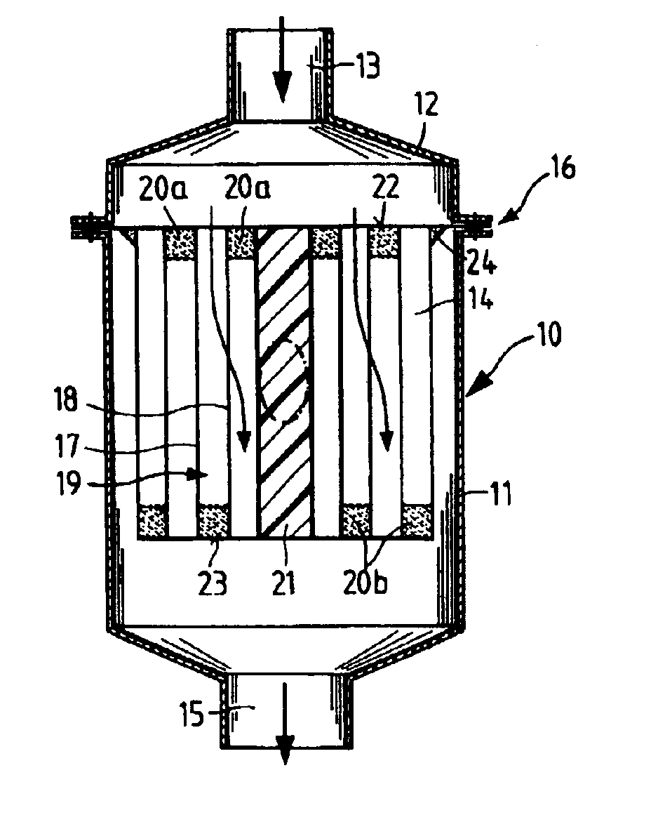
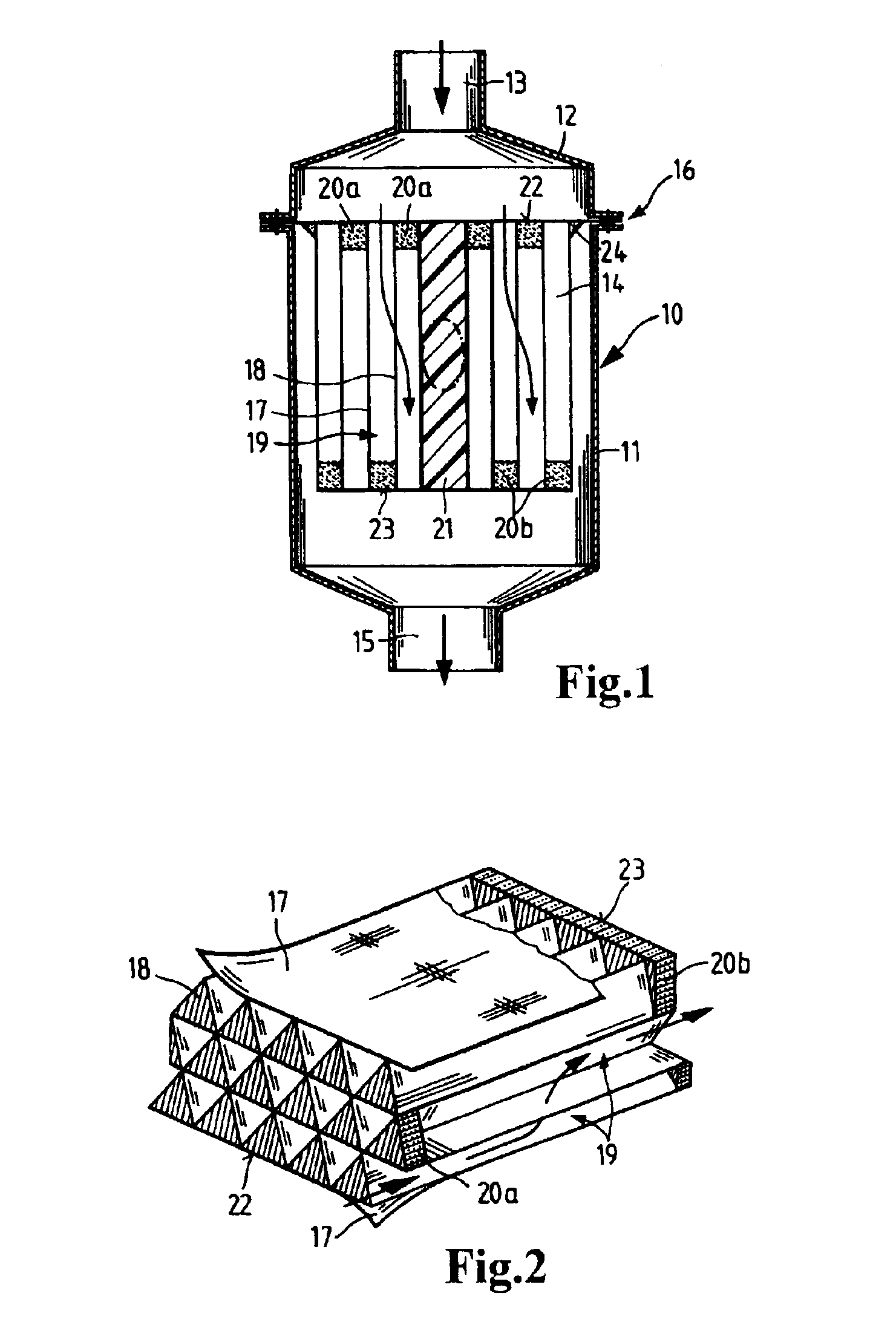
[0031]FIG. 1 depicts an inline filter with a housing 10 comprising a housing vessel 11 and a cover 12. The cover has an inlet 13 through which the fluid to be filtered flows into the housing in the direction indicated by the arrow. The fluid then flows through a filter insert 14 and through an outlet 15. Filter insert 14 is mounted in a parting plane 16 between the housing vessel 1 land the cover 12 of the housing.

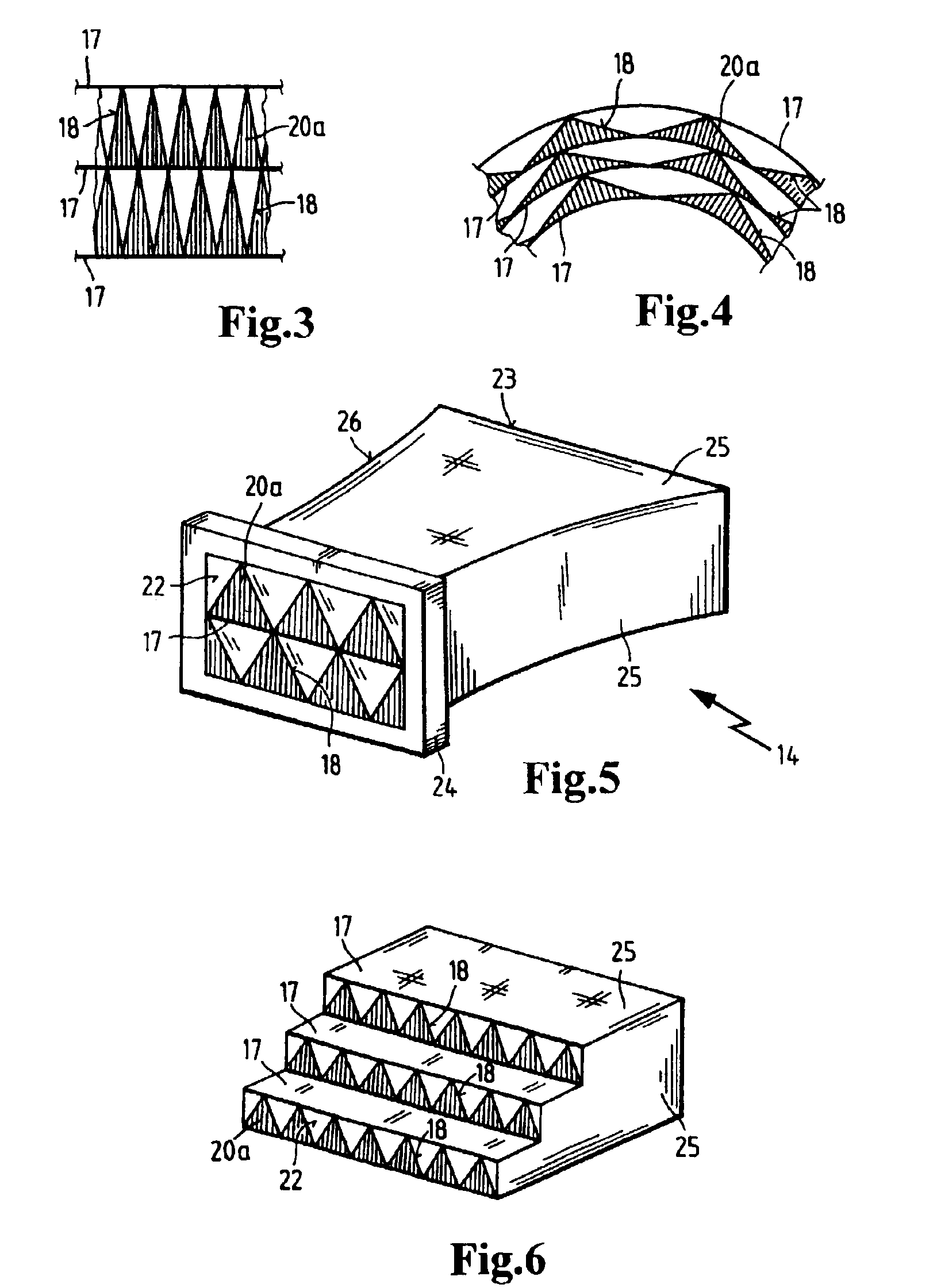
[0032]The schematically depicted filter insert 14 is configured as a wound filter. The different layers 17 and 18 form channels 19 through which the fluid to be filtered flows. The channels are alternately sealed by seals or closures 20a and 20b, so that the fluid to be filtered must switch channels as it flows through the filter insert 14. This causes the fluid to be filtered. The layers 17 and 18 are furthermore wound around a core 21 having e.g., an oval cross section, forming a seal.

[0033]To produce a reliable separation between an inlet side 22 and a discharge side 23...


PUM

PropertyMeasurementUnit
Flow rateaaaaaaaaaa
Shapeaaaaaaaaaa
Surface areaaaaaaaaaaa

Abstract

A filter element for end face inlet formed of triangular channels which are alternately closed such that the fluid to be filtered must pass through the filter material in order to flow from the inlet side (22) to the discharge side (23). The channels are formed by alternating flat layers (17) and folded layers (18), whereby all sides of the inlet channels face a discharge channel. A particularly high filter efficiency is thereby achieved such that a large filter surface area and a high filter capacity are attained with a relatively small structural volume. The filter can be used, for example, as an air filter for various air filtration applications.

Description

CROSS REFERENCE TO RELATED APPLICATIONS[0001]This application is a continuation of international patent application no. PCT / EP01 / 13401, filed Nov. 20, 2001, designating the United States of America, and published in German as WO 02 / 49741, the entire disclosure of which is incorporated herein by reference. Priority is claimed based on Federal Republic of Germany patent application no. DE 100 63 789.2, filed Dec. 24, 2000.BACKGROUND OF THE INVENTION[0002]The invention relates to a filter element for end face inflow, comprising alternating flat layers and folded layers which form channels having a triangular cross section, in which the channels are alternately sealed at one end or the other so that the fluid to be filtered must flow through the filter medium. The invention further relates to a filter in which the described filter element is installed.[0003]Filter elements with end face inlets are already known in the art. These filters are wound, for example, from filter layers that ar...

Claims


Application Information

Patent Timeline
IPC IPC(8): B01D46/24B01D46/52B01D29/07B01D46/00B01D29/00
CPCB01D46/0012B01D46/24B01D46/525B01D2275/206B01D46/52
Inventor WINTER, MANFREDGOERG, GUENTERPOH, RALF
Owner MANN HUMMEL GMBH
Why Eureka
Try Eureka