Sensor for measuring shear forces

Inactive Publication Date: 2005-10-18
GREAT LAKES NEUROTECH
View PDF21 Cites 33 Cited by
  • Summary
  • Abstract
  • Description
  • Claims
  • Application Information

AI Technical Summary

Problems solved by technology

No product has been successfully engineered to replace the shear force sensors naturally found in our skin.
There are three somewhat crude sensors or techniques that have been developed to measure shear forces to date, but each of these sensors have their own limitations.
Even if this sensor was fabricated from a flexible material and bonded to the surface where lateral movement was being measured, which would be difficult, the basic principle of this type of sensor is to measure strain, and therefore tension or compression du

Method used


Image

  • Sensor for measuring shear forces
  • Sensor for measuring shear forces
  • Sensor for measuring shear forces

Examples


Embodiment Construction

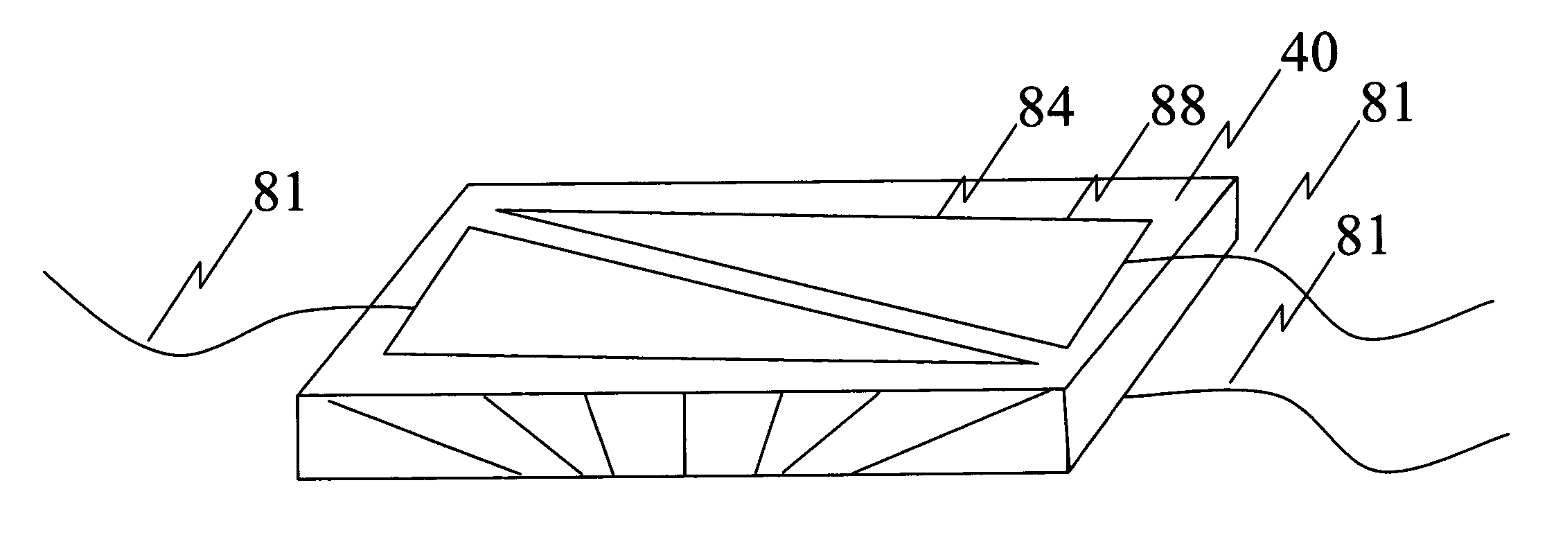
[0027]The present invention is related to a sensor for simultaneously measuring both normal and shear forces applied to the sensor, and further a statically responsive sensor for measuring shear forces. The present invention further includes a method of designing an object or a device using these sensors. The present invention encompasses numerous embodiments a number of which are set forth below.

[0028]In one embodiment, the present invention includes a sensor comprising two layers of contact material, and a flexible material interposed between the two layers of contact material; wherein the sensor can be used to simultaneously measure both shear and normal forces applied to the sensor.

[0029]In another embodiment, the present invention includes a sensor comprising at least two layers of contact material, and a flexible material interposed between the two layers of contact material; wherein at least one of the layers of contact material is formed from multiple conductive lines or reg...


PUM


Abstract

The present invention is related to a sensor for simultaneously measuring both normal and shear forces applied to two or more flexible sensors, and further a statically responsive sensor for measuring shear forces. The present invention further includes a method of designing an object, prototype or a device using these sensors to detect both shear and normal forces encountered at the sensor locations.

Description

[0001]The U.S. Government has a paid-up license in this invention and the right in limited circumstances to require the patent owner to license others on reasonable terms provided for by the terms of grant number 1R4341853-01 awarded by the National Institute of Health.BACKGROUND OF THE INVENTION[0002]1. Field of the Invention[0003]The present invention is related to a sensor for simultaneously measuring both normal and shear forces applied to the sensor, and further a statically responsive sensor for measuring shear forces. The present invention further includes a method of designing an object or a device using these sensors.[0004]2. Technical Background[0005]The need for a thin, flexible shear force sensor has been apparent in multiple fields of discipline. The ability to measure shear forces is needed in many applications including prevention of pressure sores, neural prosthesis feedback and in prosthetic limbs. No product has been successfully engineered to replace the shear for...

Claims


Application Information

Patent Timeline
IPC IPC(8): G01N3/00G01N3/24A43B5/00A43D1/02G01L1/20G01L5/22
CPCA43B5/00A43D1/02G01L1/20G01L5/228A43B3/34A61B5/0002A61B5/0024A61B5/103A61B5/1038A61B5/11A61B5/112A61B5/1126A61B5/113A61B5/68A61B5/6802A61B5/6807A63B2230/00A63B2243/00A61B2503/10A63B2230/60
Inventor TARLER, MATTHEW DAVID
Owner GREAT LAKES NEUROTECH
Why Eureka
Try Eureka