
Fast-acting clamp for a musical instrument

a technology for musical instruments and clamps, applied in the direction of instruments, scaffold accessories, music aids, etc., can solve the problems of troublesome and slow screwing of threaded rods (33/b>) in or out to attach or release brackets to or from the extending suppor

Inactive Publication Date: 2005-10-25
HSIEH WU HONG
View PDF9 Cites 31 Cited by
  • Summary
  • Abstract
  • Description
  • Claims
  • Application Information

AI Technical Summary

Problems solved by technology

Screwing the threaded rod (33) in or out to attach or release the bracket to or from the extending support is troublesome and slow.

Method used


Image

  • Fast-acting clamp for a musical instrument
  • Fast-acting clamp for a musical instrument
  • Fast-acting clamp for a musical instrument

Examples


Embodiment Construction

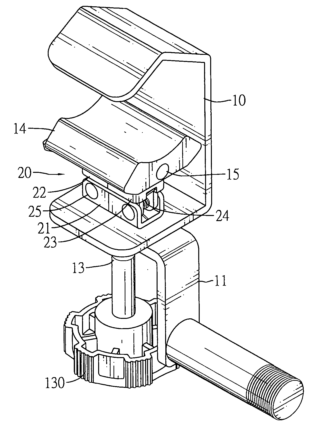
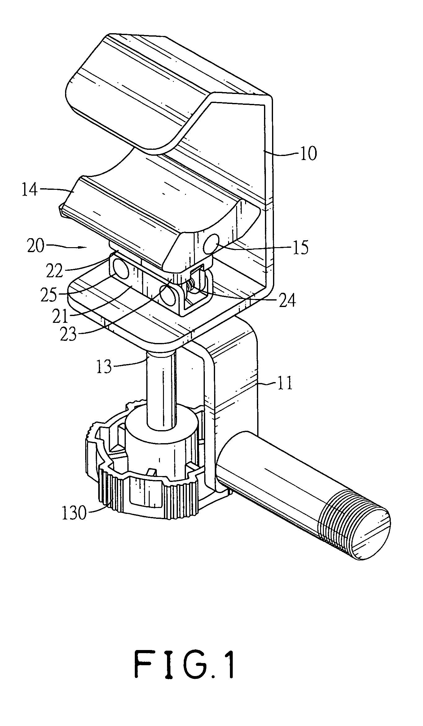
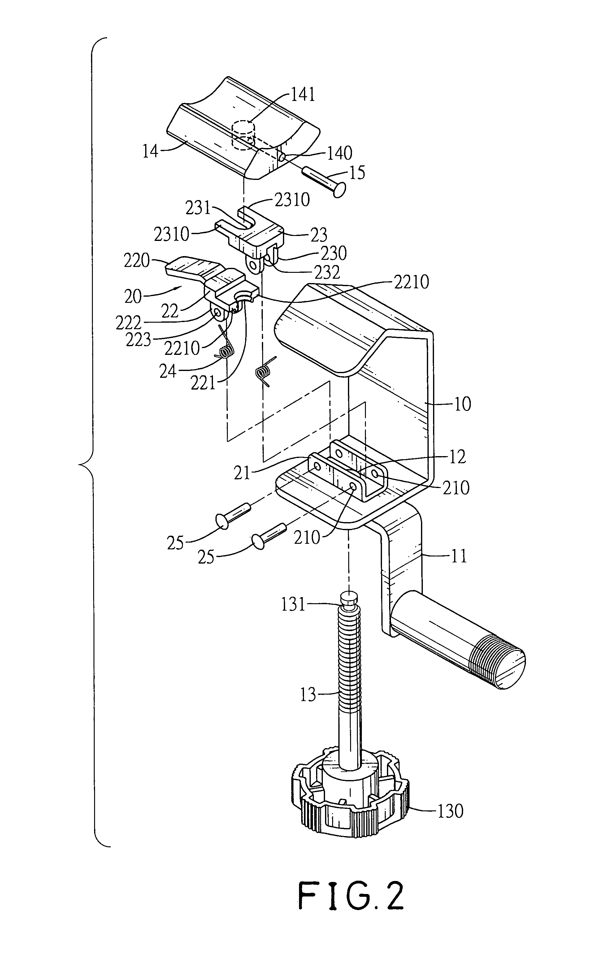
[0013]With reference to FIGS. 1 and 2, a fast-acting clamp for a musical instrument in accordance with the present invention comprises a bracket (10), a connector (11), a threaded rod (13), a positioning assembly (20) and an optional moveable jaw (14).

[0014]The bracket (10) is U-shaped and has a proximal side, a distal side and a through hole (12). The proximal side has an outside surface and an inside surface. The through hole (12) is formed through the proximal side.

[0015]The connector (11) is attached to the bracket (10), may be L-shaped and may have a longitudinal leg and a transverse leg. The transverse leg is attached to the outside surface of the proximal side of the bracket (10).

[0016]The threaded rod (13) extends through the through hole (12) in the bracket (10) and has a distal end, a proximal end, an outer surface, a knob (130), a thread and an optional neck (131). The proximal end extends through the through hole (12) in the bracket (10). The knob (130) is attached to th...


PUM


Abstract

The fast-acting clamp for a musical instrument is selectively attached to an extending support and has a bracket, a connector, a threaded rod and a positioning assembly. The bracket is U-shaped. The connector is attached to the bracket. The threaded rod extends through the bracket. The positioning assembly has a base, a primary retainer, a secondary retainer and two springs. The base is attached to the bracket. The primary retainer is mounted pivotally on the base and has a tab, a semicircular notch and two edges. The secondary retainer is mounted pivotally on the base and has a semicircular notch and two edges. The springs connect to the base and the retainers to press the retainers inward. The tab is pressed to release the threaded rod so the fast-acting clamp can be quickly attached to or released from an extending support.

Description

BACKGROUND OF THE INVENTION[0001]1. Field of the Invention[0002]The present invention relates to a fast-acting clamp, especially to a fast-acting clamp for a musical instrument.[0003]2. Description of the Prior Arts[0004]With reference to FIG. 5, a conventional clamp used to mount a musical instrument on an extending support comprises a U-shaped bracket (30), an L-shaped connector (31), a threaded rod (33) and a knob (34). The bracket (30) has a proximal side, a distal side and a through hole. The through hole is formed in the proximal side. The L-shaped connector (31) has a longitudinal leg and a transverse leg. The longitudinal leg is attached to the proximal side of the bracket (30) and has a threaded hole (32) corresponding to the through hole. The threaded rod (33) extends through the through hole, screws through the threaded hole (32) and has a proximal end. The knob (34) is mounted on the proximal end and is rotated to screw the threaded rod (33) into or out of the threaded h...

Claims


Application Information

Patent Timeline
Patent Type & Authority Patents(United States)
IPC IPC(8): A47G1/06A47G1/10A47B96/06F16B2/12F16B37/08F16M13/02
CPCF16B2/12F16B37/0821F16M13/02F16M13/022
Inventor HSIEH, WU-HONG
Owner HSIEH WU HONG
Learn More