Lift-type positioning structure for bracket of computer interface card

a technology of computer interface cards and positioning structures, which is applied in the direction of electrical apparatus casings/cabinets/drawers, coupling device connections, instruments, etc., can solve the problems of leakage of electromagnetic waves, inconvenient assembly and disassembly of interface cards, and a larger depth of housings

Inactive Publication Date: 2005-11-01
SHUTTLE
View PDF7 Cites 40 Cited by
  • Summary
  • Abstract
  • Description
  • Claims
  • Application Information

AI Technical Summary

Problems solved by technology

However, the housing has a larger depth to waste a lot of space.
It is very inconvenient for assembling and dissembling the interface card, particularly for those who install and remove interface cards into and from a computer frequently.
Many of the users will just remove the shields to result in leakage electromagnetic wave.
However, such type of lid still requires fasteners such as screw to be secured to the housing, and the user has to continuously lift the lid allowing the through hole to be exposed.

Method used


Image

  • Lift-type positioning structure for bracket of computer interface card
  • Lift-type positioning structure for bracket of computer interface card
  • Lift-type positioning structure for bracket of computer interface card

Examples


Embodiment Construction

[0017]Reference will now be made in detail to the preferred embodiments of the present invention, examples of which are illustrated in the accompanying drawings. Wherever possible, the same reference numbers are used in the drawings and the description to refer to the same or like parts.

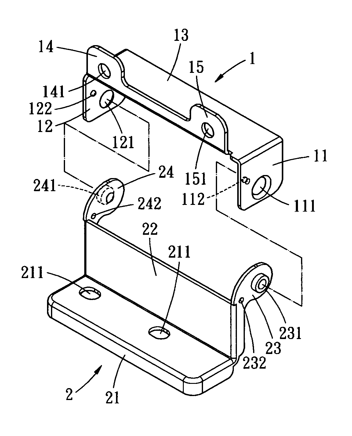
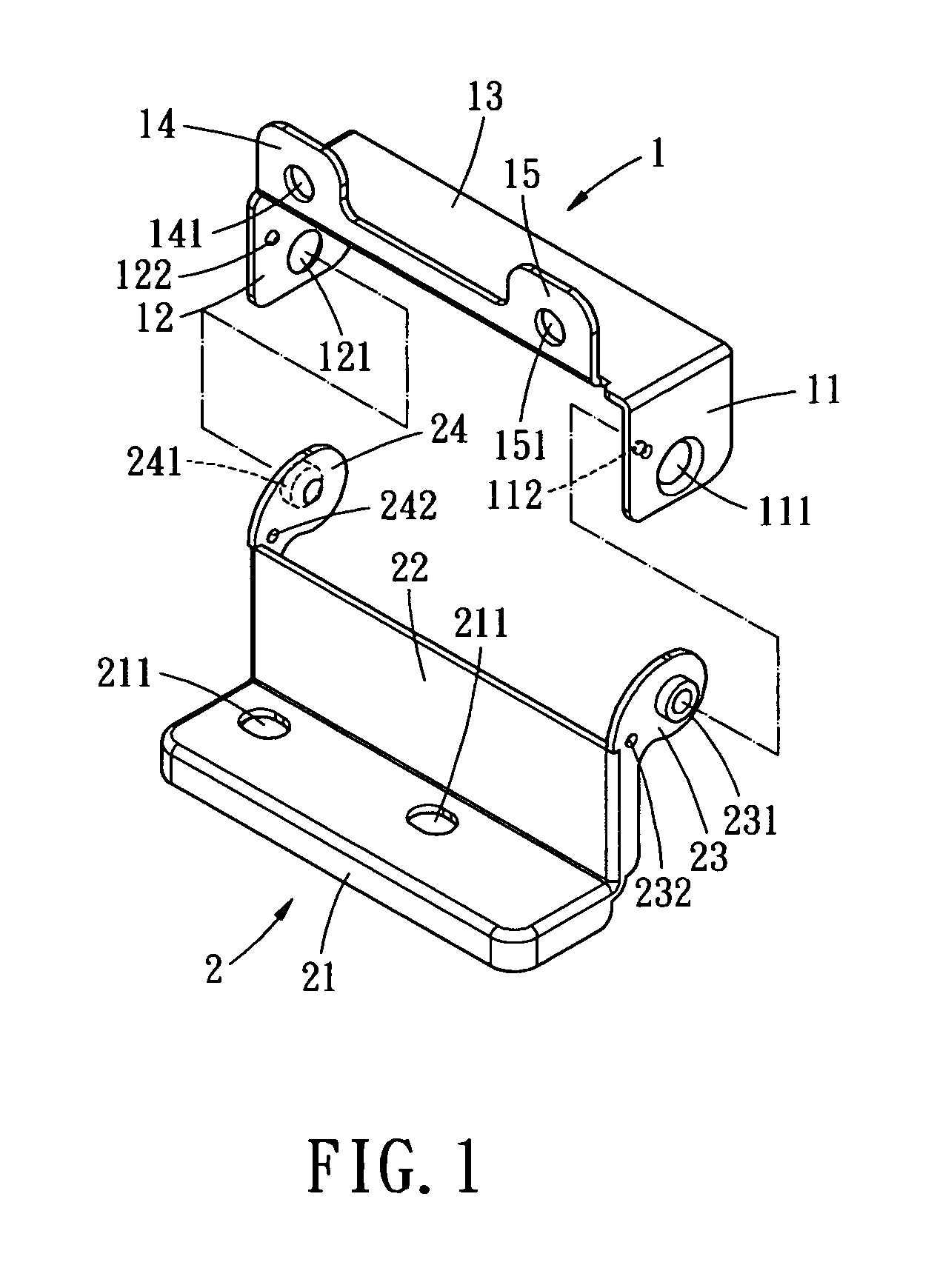
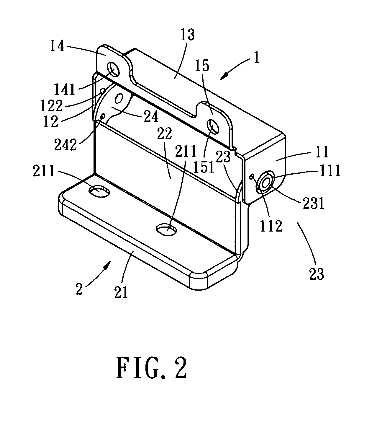
[0018]As shown in FIG. 1, the first embodiment of the present invention includes a seat member 1 and a lid 2. The seat member 1 is to be mounted to a backplane of a computer housing at a through hole penetrating through the backplane. The seat member 1 includes an elongate horizontal plate 13 and two vertical end plates 11, 12 extending perpendicularly from two opposing ends of the elongate plate. The side plates 11 and 12 are perforated with axial apertures 111 and 121 aligned with each other. The end plates 11 and 12 further comprise protruding spots 112 and 122 extending from inner surfaces thereof towards each other. The protruding spots 112 and 122 are located offside of the axial apertures 111 ...


PUM


Abstract

A lift-type positioning structure for a lid of a bracket of a computer interface card havs a housing, a seat member, a lid and a positioning structure. The housing has a receiving slot for receiving the interface card, a rectangular slot over the receiving slot, and a horizontal platform extending perpendicularly from a lower edge of the rectangular slot. The seat member is mounted to the housing at an edge of the rectangular slot. The lid is pivotally connected to the seat member to be lifted up or down. The positioning device is operative to secure the lid at an open position.

Description

BACKGROUND OF THE INVENTION[0001]The present invention relates to a lift-type positioning structure for a lift-type bracket of a computer interface card, and more particular, to a lift-type lid suitable for use in a protruding positioning structure for a bracket of a computer interface card, so as to cover through holes of the computer housing.[0002]The interface card is basically constructed by a circuit board that has a gold finger and an inverse L-shape bracket. The bracket is locked with a window frame structure, which is typically referred as “rear window”, by screws. The window frame has at least one or a plurality of slots for accommodating vertical body of the bracket which connectors formed thereon. To comply with the horizontal body of the bracket, the window frame has a horizontal platform for locking the bracket. Therefore, the rear of the housing includes recessed and protruding designs. The former includes a recessed window frame, and the recessed portion constructs th...

Claims


Application Information

Patent Timeline
Patent Type & Authority Patents(United States)
IPC IPC(8): H02G3/08G06F1/18
CPCG06F1/186
Inventor WEN-LUNG, YU
Owner SHUTTLE
Why Eureka
Try Eureka