Hair styler

a hair styler and hair technology, applied in the field of hair stylers, can solve the problems of hair styles that are presently formed, and none of the devices of the disclosed art are disposed to provide braids and twists

Inactive Publication Date: 2005-11-08
ADAM MICHAEL
View PDF5 Cites 59 Cited by
  • Summary
  • Abstract
  • Description
  • Claims
  • Application Information

AI Technical Summary

Benefits of technology

[0013]In another embodiment, a small wire hook is mounted on the apex of the cone and extends in the ax...

Problems solved by technology

None of the devices of the disclosed art are disposed to provide the braids and twists that characterize styles that are desired in the present...

Method used


Image

  • Hair styler
  • Hair styler
  • Hair styler

Examples


Embodiment Construction

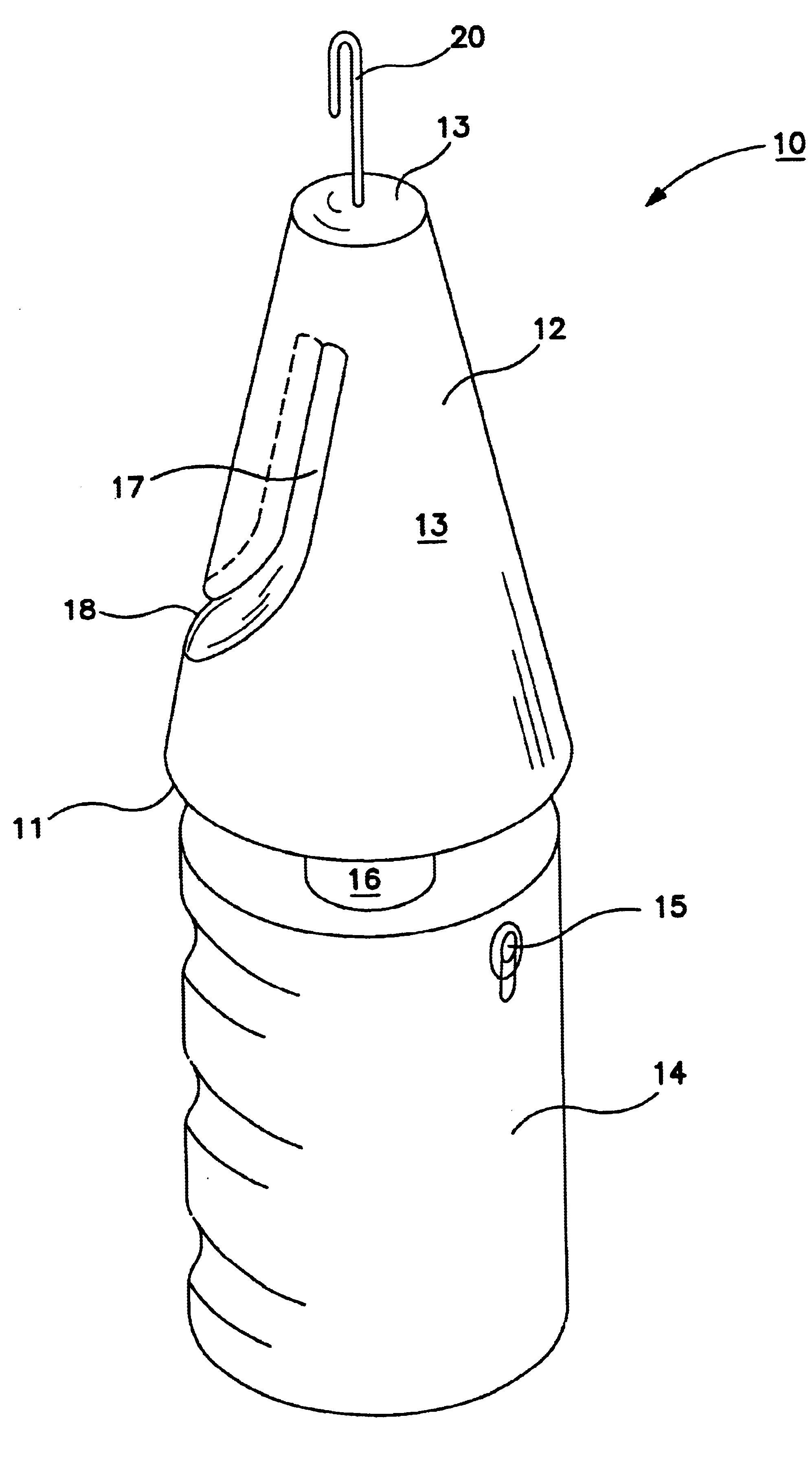
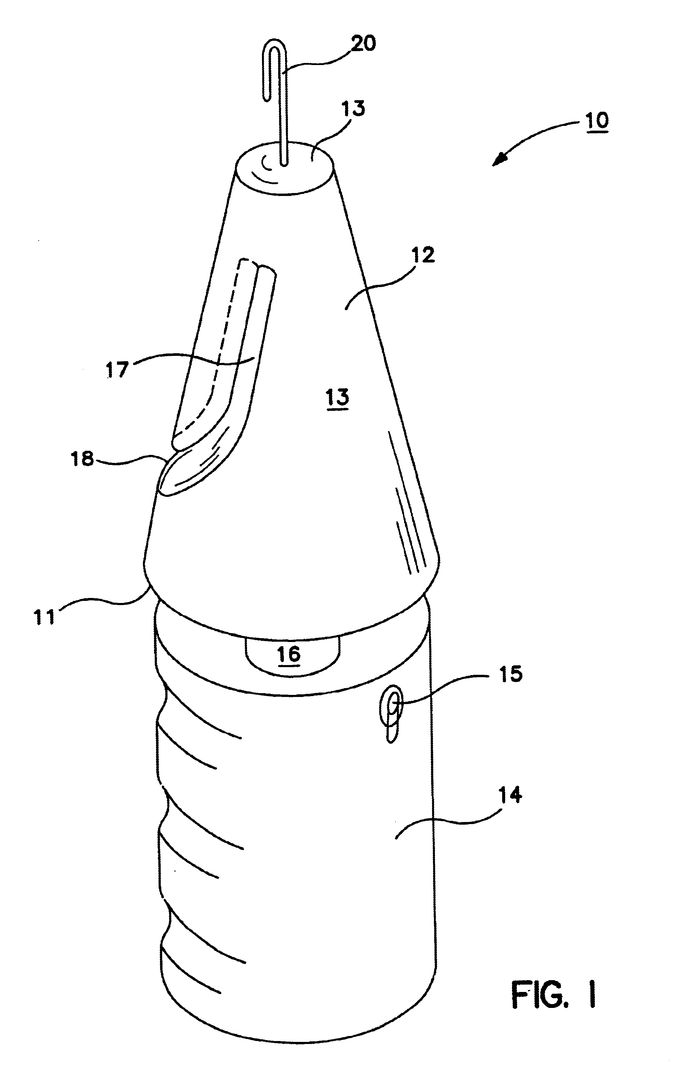
[0028]Turning now to a discussion of the drawings, FIG. 1 shows the hair styler 10 of this invention.

[0029]There are shown a truncated cone 12 and a handle section 14. The cone 12 has a conical surface 13 with a base surface 11 on one end and an apex 13 on the other end. The handle section 14 houses a motor (motor not shown). The motor is preferably driven by a battery positioned inside the handle section 14. The shaft 16 of the motor protrudes from the handle section 14.

[0030]The base 11 of the cone 12 is mounted on the protruding shaft 16 so that axial rotation of the cone is under control of the user by a switch 15 on the handle that permits stopping and starting rotation and rotation in either one of two directions.

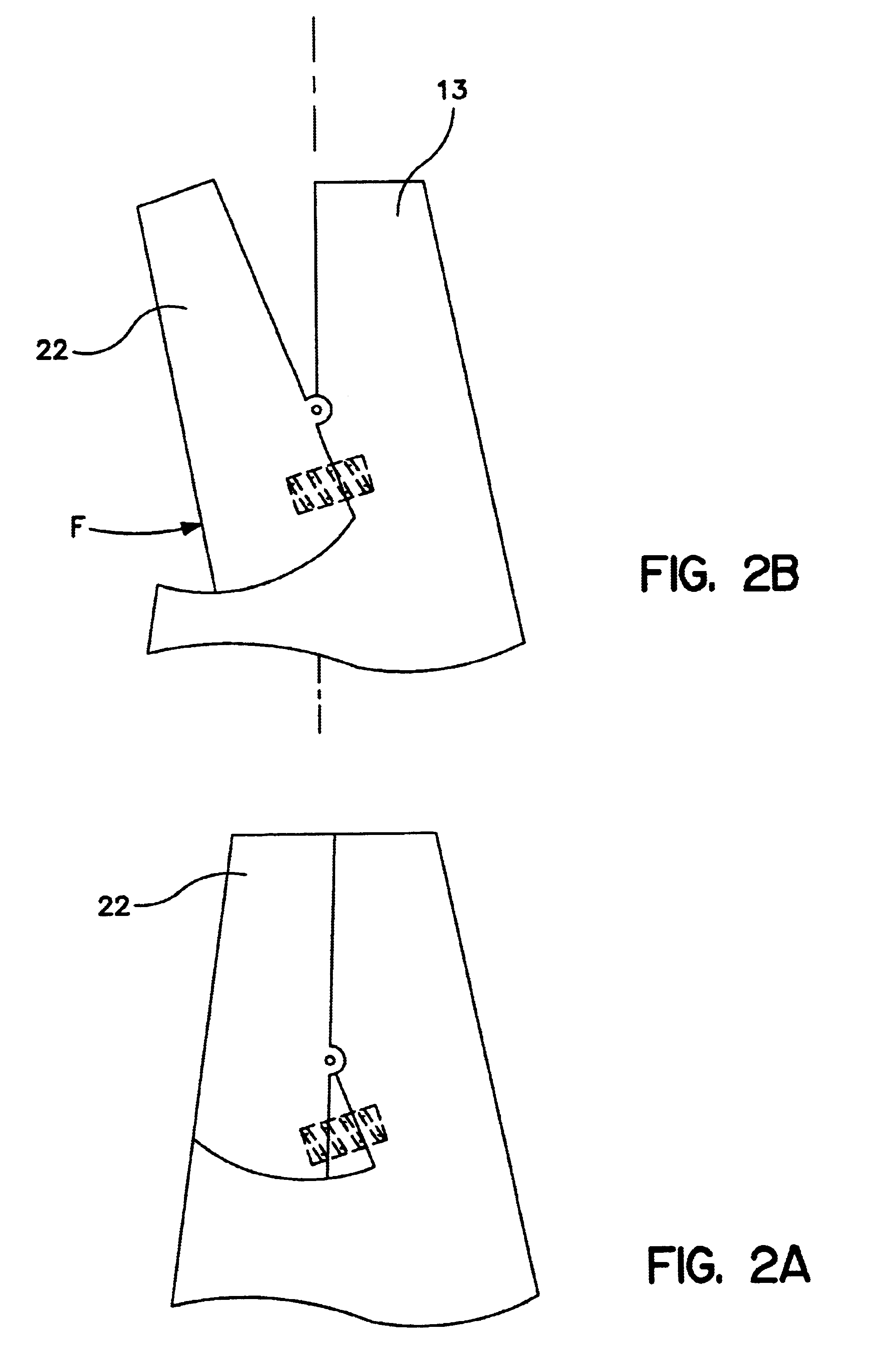
[0031]The cone 12 has a elongated slot 17 extending axially and entirely through the cone 12 with an opening 18 in the side of the cone 12 near the base 11.

[0032]In one embodiment, a hook 20 is mounted on the apex end of the cone as shown in FIG. 1.

[0033]In another em...


PUM


Abstract

A cone mounted coaxially on a hand held motor. The cone has an open slot arranged to permit sliding a lock of hair through the slot. The lock wraps around the cone thereby forming a roll of hair when the motor is energized to rotate the cone. The cone is then separated from the roll and the hair is secured in place by a pin. A clamp/hook on the apex of the cone is provided to engage the free end of a lock of hair, a twist of hair (akin to a cable) is formed when the cone is rotated.

Description

FIELD OF THE INVENTION[0001]This invention relates to devices and methods for styling women's hair and particularly to a device with which a hair styler is enable to form unusual and intricate hair styles.BACKGROUND AND INFORMATION DISCLOSURE[0002]Hair styling is an art form that has been practiced since the beginning of civilization. The average woman typically has a strong interest in arranging her hair in a design that is attractive, unique and “stylish”.[0003]By stylish is meant that certain hair styles have characteristics that identify arrangements that are very similar to one another and which are commonly seen during certain periods throughout history or which have been adopted by a particular ethnic or cultural group.[0004]By unique is meant that, within any style, the wearer still endeavors to be distinguishable from other members wearing the same style.[0005]Numerous tools have been developed with which the hair stylist is enabled to arrange hair according to the desired ...

Claims


Application Information

Patent Timeline
IPC IPC(8): A45D6/00A45D6/02
CPCA45D6/02
Inventor ADAM, MICHAEL
Owner ADAM MICHAEL
Why Eureka
Try Eureka