Rotatable tool assembly

a tool body and rotating technology, applied in the direction of cutting machines, earthwork drilling and mining, etc., can solve the problems of wear or wash away of the material which makes up the tool body, the need to replace the tool body, and the need for the tool body to wear evenly around the circumferen

Inactive Publication Date: 2005-11-22
THE SOLLAMI COMPANY
View PDF4 Cites 114 Cited by
  • Summary
  • Abstract
  • Description
  • Claims
  • Application Information

AI Technical Summary

Benefits of technology

[0013]In accordance with the invention, a washer having an inner annular surface having a diameter which is greater than the diameter of the transverse hole into which the shank and retainer sleeve are inserted is fitted around the shank of the tool and the retainer sleeve thereon. Bonded to the inner annular surface of the washer is a rubberized annular elastomeric member, the outer circumference of the annular elastomeric member being bonded to the inner surface of the washer such that the washer and an annular elastomeric member form a single part. The annular elastomeric member has an inner diameter that is less than that of the inner diameter of the cylindrical hole in the tool holder. Accordingly, when the washer with the annular elastomeric member bonded thereto is fitted over the shank of the tool and the retaining sleeve, the compressible qualities of the annular elastomeric member will retain the part (washer and annular elastomeric member) from falling off the end of the shank, thereby retaining the parts in their desired relationship until the tool is placed in use.

Problems solved by technology

As the machine cuts hard material, such as concrete or asphalt, fragments of the broken material are forced across the tapered forward end of the tool and around the sides of the mounting block causing wear, or wash away, of the material which make up both the tool body and the mounting block.
As a result of such improvements, as many as one hundred tools may be worn out before a mounting block suffers such wear that it, too, must be replaced.
The tools used in such machines are symmetric about their longitudinal axis and the rotation of the tool within the cylindrical mounting causes the tool body to wear evenly around its circumference.
Even so, such tools become worn very rapidly and it is common to replace all of the tools on a machine after a single day of usage.
A tool which does not rotate properly, however, will fail prematurely and the failure of several tools on a machine can cause the machine to be taken out of service before completion of a day's work.
Certain new problems are created, however, by the provision of a washer.
If the washer is not properly centered on the tool while it is being inserted into the retainer or tool block, the washer will prevent the tool from being properly seated in its holder.
An improperly seated tool will not rotate properly, and will contribute to the premature failure of the tool holder.
Where the tool holder is provided with a polished forward surface, the washer may tend to rotate with the tool and thereby defeat its purpose.

Method used


Image

  • Rotatable tool assembly
  • Rotatable tool assembly
  • Rotatable tool assembly

Examples


Embodiment Construction

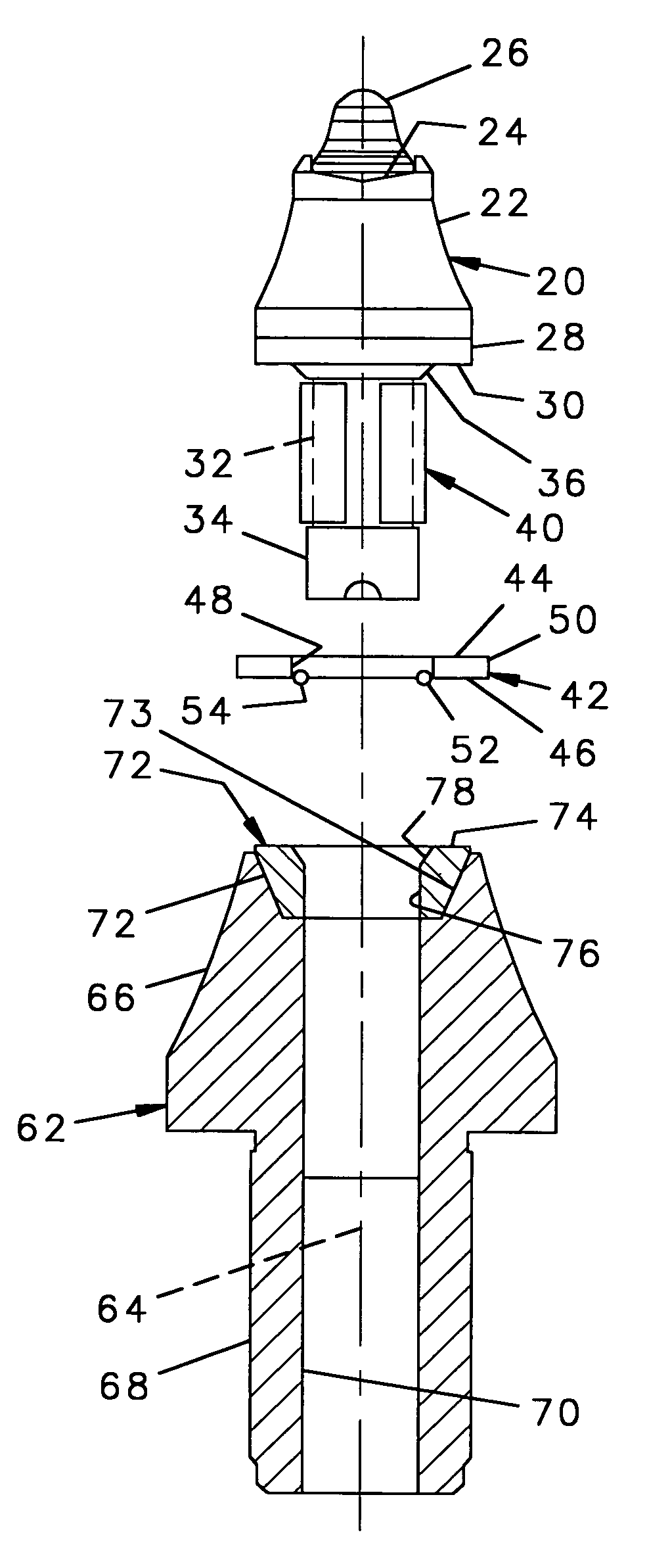
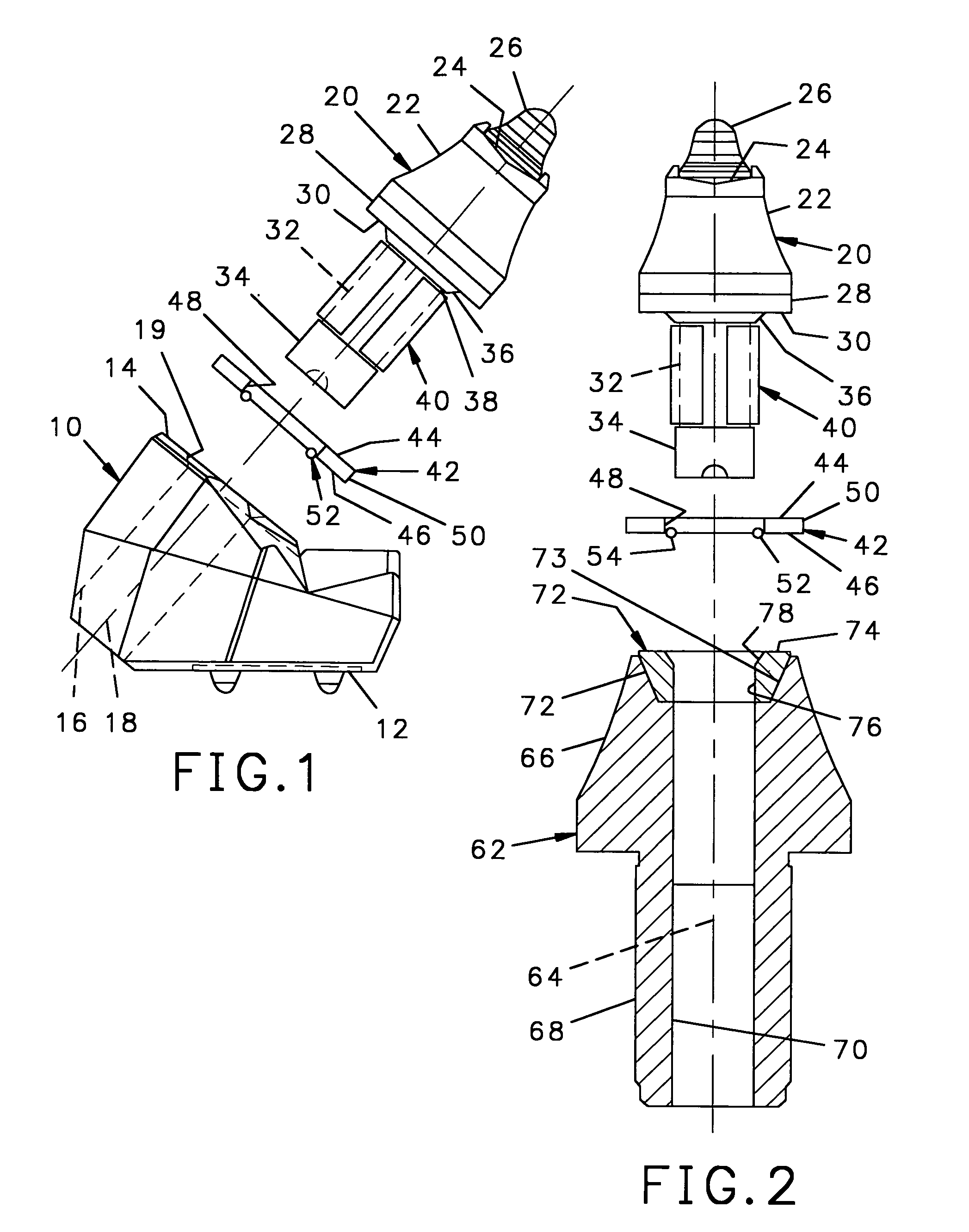
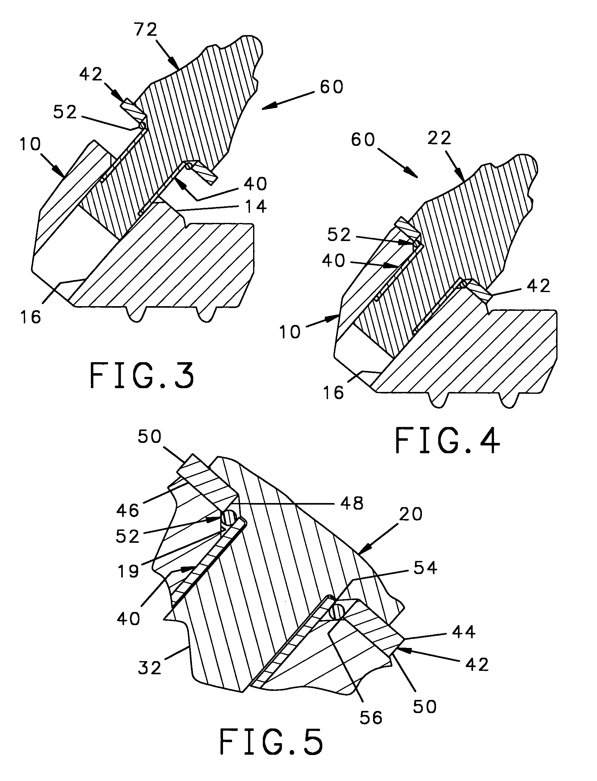
[0023]Referring to FIG. 1, a tool holder or mounting block 10 is made of alloy steel and has an alignment portion 12 to align the block 10 as it is welded to the rotating member (not shown) of a machine. The block 10 further has a planar forward surface 14 and extending through the body of the block is a transverse hole 16 having a longitudinal axis 18 perpendicular to the forward surface 14. Near the forward surface 14 and surrounding the end of the hole 16 is a frustoconical counter sink 19 to facilitate the alignment of a tool as it is inserted into the block 10.

[0024]Referring to FIGS. 1, 3, 4 and 5, received within the transverse hole 16 is a tool 20 having a tapered forward end 22, at the most forward end of which is seat 24 into which is fitted a tungsten carbide insert 26. Rearward of the tapered forward end 22 is a radial flange 28, having a planar rear surface 30. Positioned axially behind the planar rear surface 30 is cylindrical shank 32 having an enlarged hub 34 at the ...


PUM


Abstract

A tool assembly includes an axially symmetric tool having a tapered forward end, a radial flange, and a cylindrical shank. A retainer is fitted around the cylindrical shank, a washer is fitted around the retainer, and an annular elastomeric member is bonded to the inner surface of the washer. When the rotatable shank is fitted into a cylindrical mounting bore of a tool holder, the annular elastomeric member prevents the washer from rotating with the tool.

Description

[0001]This is a continuation in part of my previously filed application Ser. No. 10 / 345,562 filed Jan. 16, 2003 now U.S. Pat. No. 6,863,352, which in turn claimed priority from my previously filed provisional application filed Jan. 24, 2002 and assigned Ser. No. 60 / 352,112. The present invention relates to a mounting for rotatable tools used to cut hard surfaces and, in particular, to an improved mounting having a washer to protect portions of the mounting block that retains the tool and having an annular elastomeric member for centering the washer.BACKGROUND OF THE INVENTION[0002]A machine for cutting hard surfaces has a rotatable member such as a wheel or a drum which turns about an axis and has a plurality of cutting tools mounted on the rotatable member. To advance the cut, the rotating member is applied against the hard surface such that each tool removes a small portion of hardened material.[0003]To maximize their useful life, the cutting tools are rotatably mounted about a lo...

Claims


Application Information

Patent Timeline
Patent Type & Authority Patents(United States)
IPC IPC(8): E21C35/00E21C35/197
CPCE21C35/197
Inventor SOLLAMI, PHILLIP A.
Owner THE SOLLAMI COMPANY
Why Eureka
Try Eureka