Card socket

Inactive Publication Date: 2005-11-22
JAPAN AVIATION ELECTRONICS IND LTD
View PDF8 Cites 26 Cited by
  • Summary
  • Abstract
  • Description
  • Claims
  • Application Information

AI Technical Summary

Benefits of technology

[0004]Therefore, it is an object of the present invention to provide a card socket

Problems solved by technology

However, there is a problem o

Method used


Image

  • Card socket
  • Card socket
  • Card socket

Examples


Example

[0030]Referring to FIGS. 1 to 23, a card socket according to an embodiment of the present invention is described in detail below.

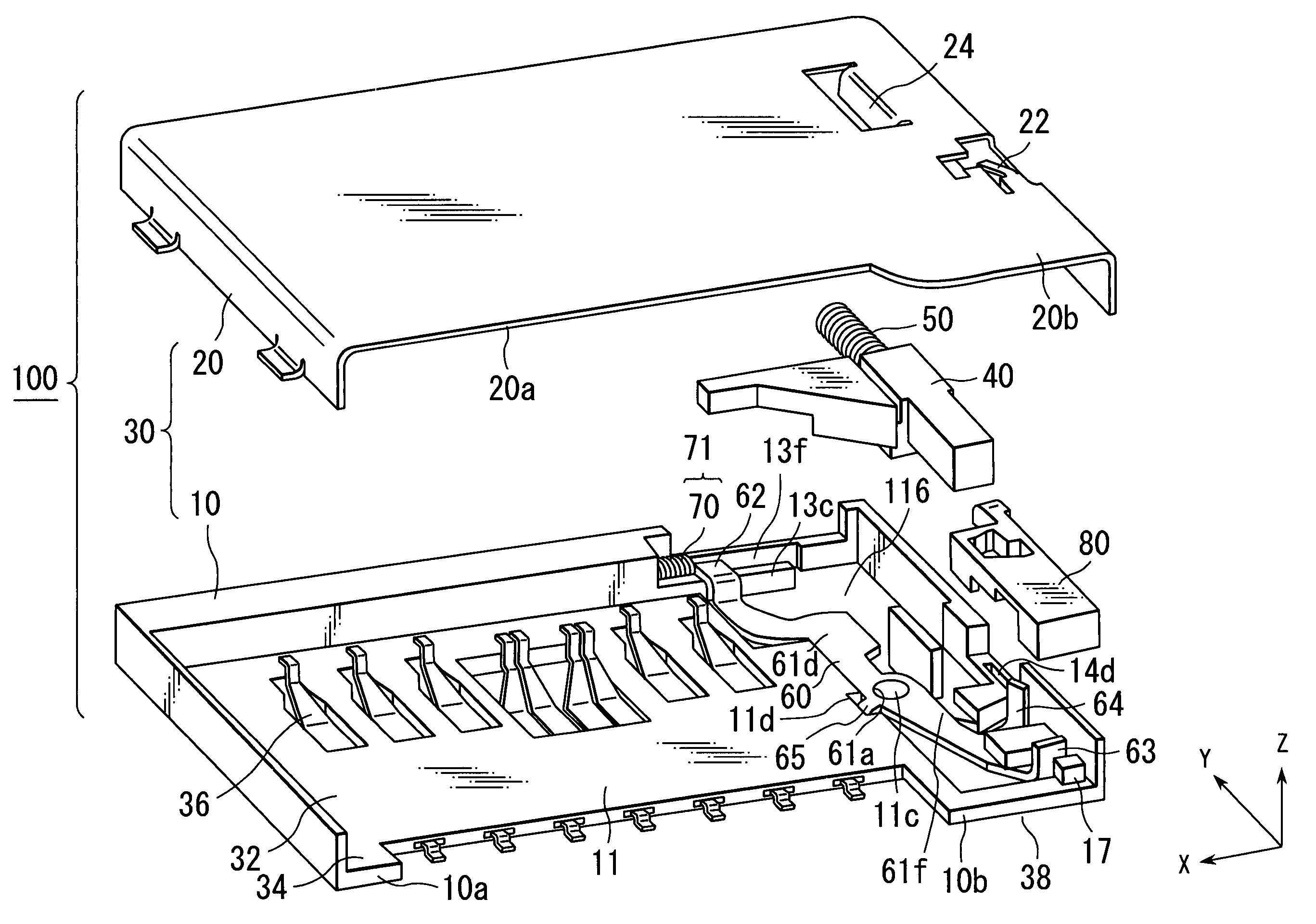
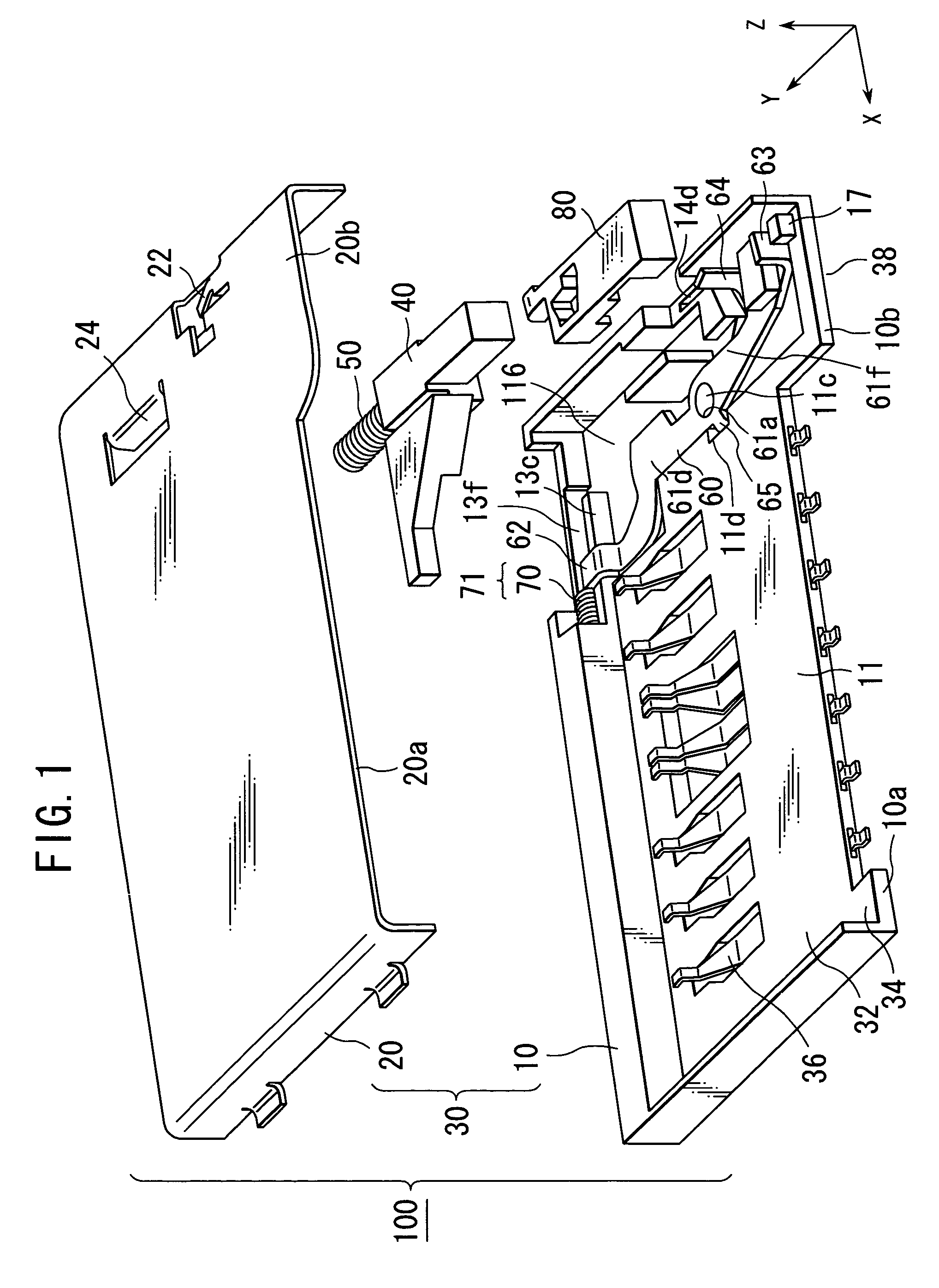
[0031]As shown in FIG. 1, the card socket 100 according to the present embodiment of the present invention comprises a case 30, a slider 40, a first compression spring 50, a rocker arm 60, a second compression spring 70 and a button 80.

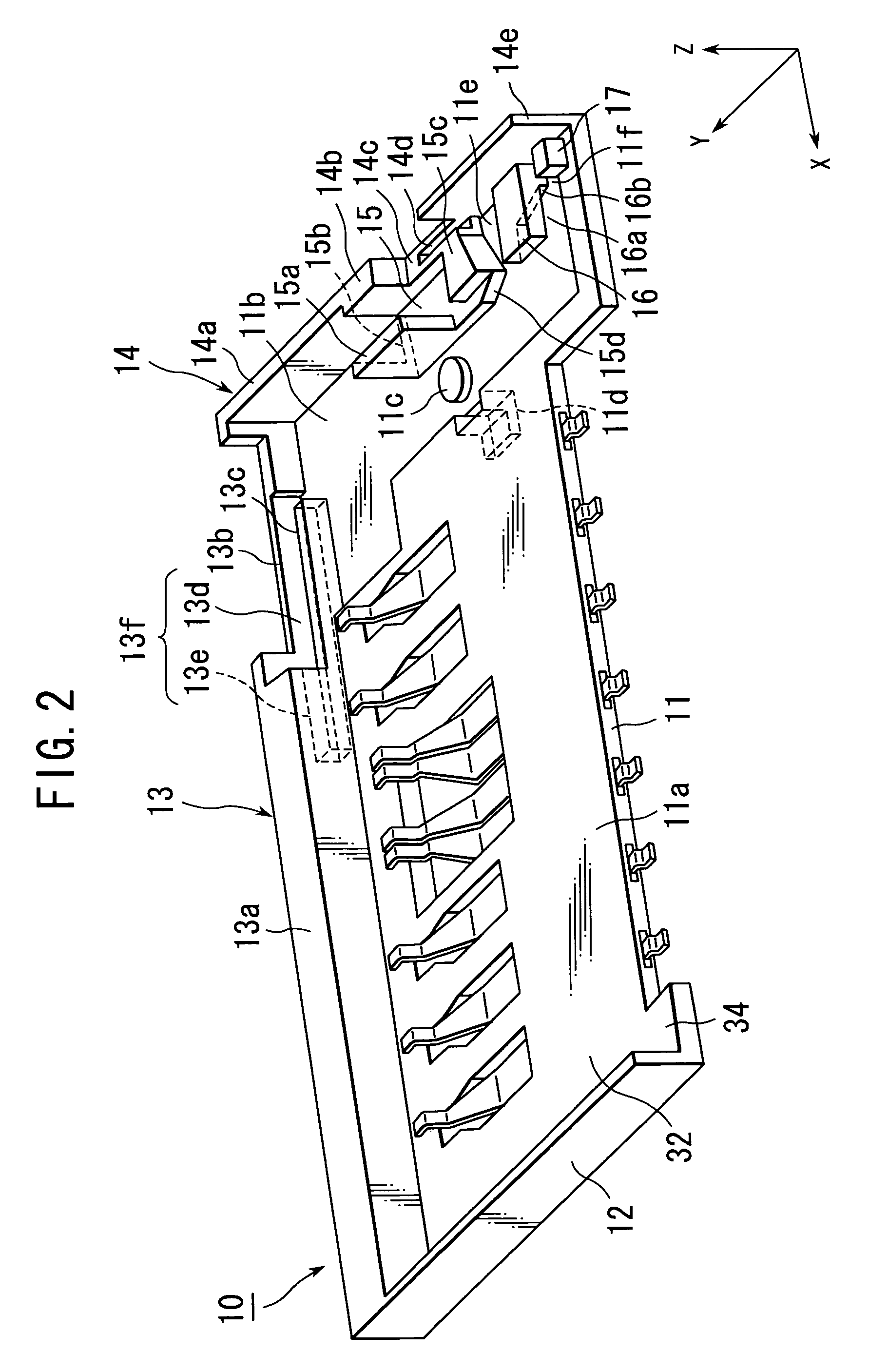
[0032]The case 30 comprises an insulator 10 and a cover 20. The insulator 10 comprises an edge 10a, a portion 10b, and a bottom portion 11. The edge 10a constitutes a rear end of the insulator 10 in a Y-direction. The portion 10b further projects outwardly of the insulator 10 in comparison with the edge 10a. The cover 20 comprises an edge 20a and a portion 20b. The edge 20a constitutes a rear end of the cover 20 in the Y-direction. The portion 20b further projects outwardly of the cover 20 in comparison with the edge 20a. The bottom portion 11 and the cover 20 define a card housing space 32, which can accommodate a card. The...


PUM


Abstract

A card socket 100 comprises a slider 40 and a rocker arm 60. The slider 40 is slidable in a card insertion/ejection direction. The rocker arm 60 comprises a fulcrum 61a, a first pressed portion 62 and a second pressed portion 64. The fulcrum 61a is provided between the first pressed portion 62 and the second pressed portion 64. When a first force is provided to the first pressed portion 62, the rocker arm 60 slides toward the slider 40 and prevents the slider 40 from sliding in the card ejection direction. When a second force is provided to the second pressed portion 64, the rocker arm 60 releases the slider 40d. Then, the slider 40 slides in the card ejection direction.

Description

BACKGROUND OF THE INVENTION[0001]The present invention relates to a card socket which contains a card ejection mechanism. The card socket is also referred to as a card connector.[0002]A small-sized device, such as a cellular phone and a digital camera, comprises a card socket for removably holding a small-sized memory card, which is smaller than a PC card.[0003]For example, a card socket of this type is disclosed in JP-A2001-351735, which is incorporated herein by reference in its entirely. The card socket comprises a card ejection mechanism and an operation member. The card ejection mechanism is activated when the operation member is moved along a thickness direction of the card socket. To block undesirable movement of the card ejection mechanism, the card socket further comprises a specific structure, which is disclosed in JP-A 2001-351735, for example, paragraph 0046. However, there is a problem of lack of the operationality.SUMMARY OF THE INVENTION[0004]Therefore, it is an objec...

Claims


Application Information

Patent Timeline
IPC IPC(8): H01R13/62G06K13/08
CPCG06K13/08G06K13/0806
Inventor MOTOJIMA, JOESUZUKI, KEIICHIRO
Owner JAPAN AVIATION ELECTRONICS IND LTD
Why Eureka
Try Eureka