Stereoscopic image display device without glasses

a display device and stereoscopic technology, applied in the field of stereoscopic image display devices, can solve problems such as inability to ensure the stereoscopic view

Inactive Publication Date: 2005-11-29
SANYO ELECTRIC CO LTD
View PDF7 Cites 74 Cited by
  • Summary
  • Abstract
  • Description
  • Claims
  • Application Information

AI Technical Summary

Benefits of technology

[0014]When a right eye image is outputted from a position for outputting a left eye image originally in one of the areas and the right eye image passes between the shading parts normally arranged, and a right eye image passes between the shading parts shifted by ¼ pitch from the other area, an area for supplying the right eye image shifts in back or forth direction f

Problems solved by technology

When these systems are used for structuring a stereoscopic image display device autostereoscopic image display device, the display device is generally structured so as to be a two-eye syste

Method used


Image

  • Stereoscopic image display device without glasses
  • Stereoscopic image display device without glasses
  • Stereoscopic image display device without glasses

Examples


Embodiment Construction

)

[0057]Explanation is made on embodiments of the present invention by referring to FIGS. 9-25.

(Outline)

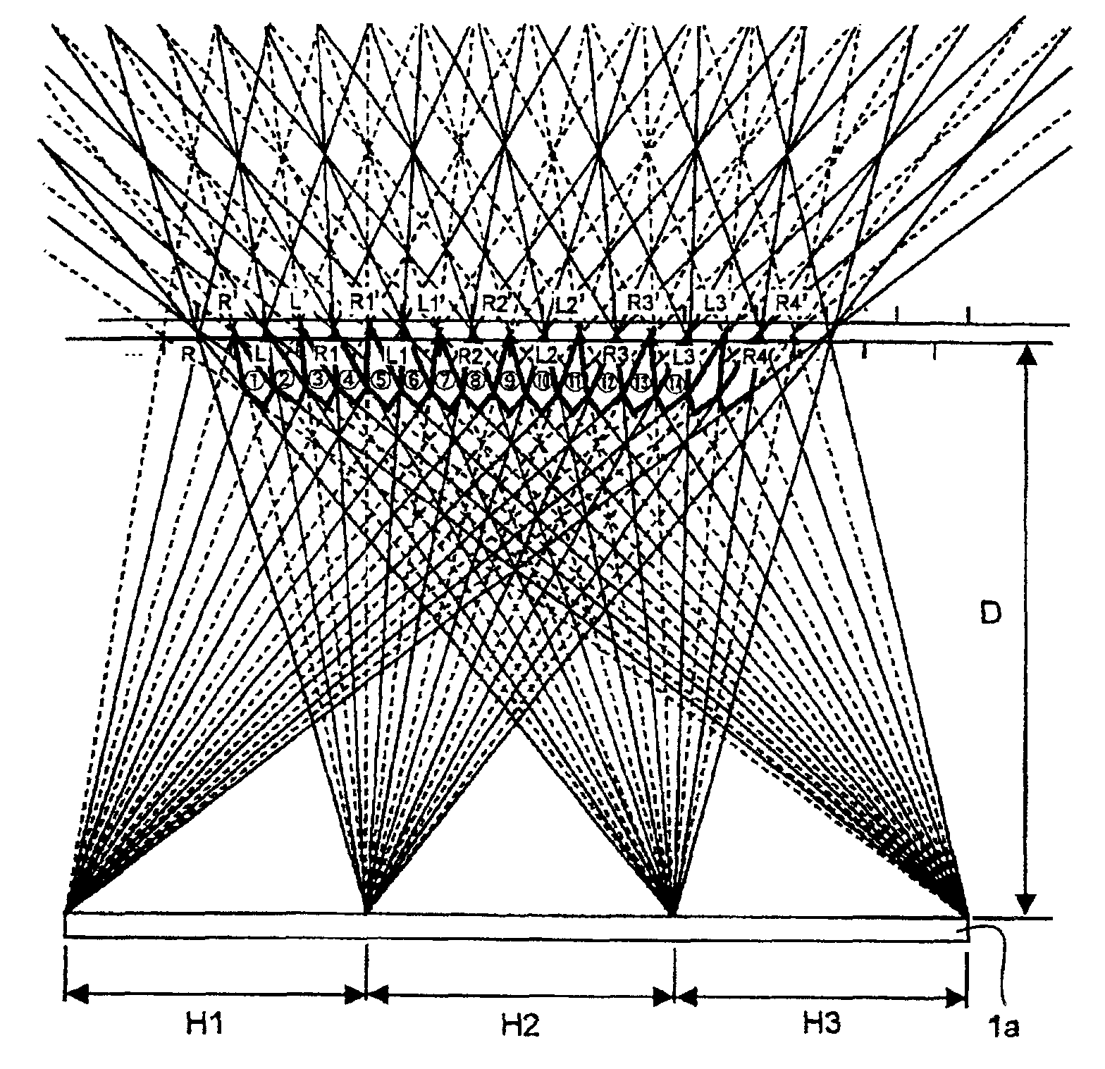
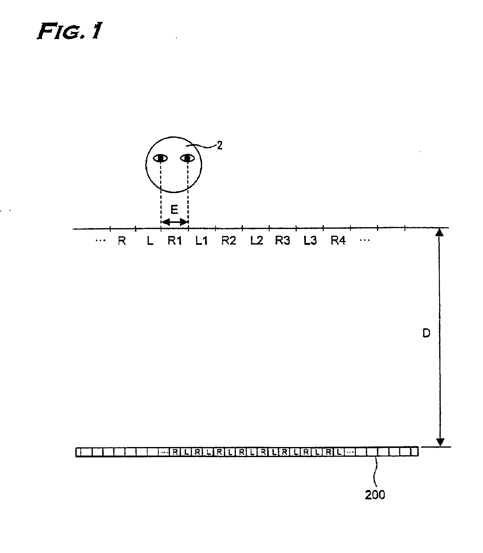
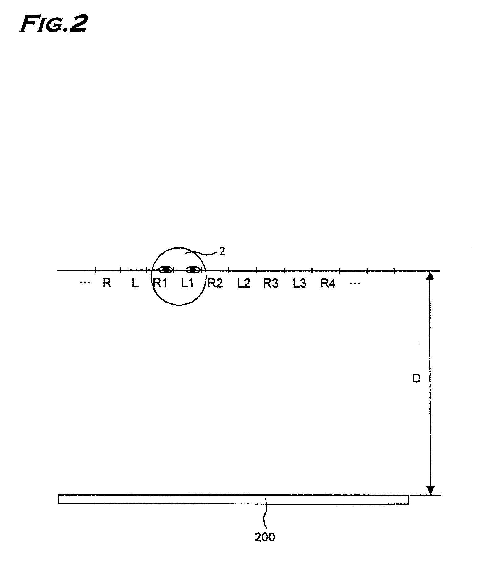
[0058]A stereoscopic image display device autostereoscopic image display device according to the embodiment is structured so that a shading part of shading means for generating binocular parallax effect shifts by ¼ of a pitch of the shading part as shown in JP9-197344, A. With this structure, the shading means is divided into areas in a horizontal direction and the number of divided areas and whether or not the shading parts are shifted by ¼ of its pitch in each of the areas are determined, and displaying of an image on a display area corresponding to the above area is controlled.

[0059]FIG. 9 illustrates the viewer 2 watching a stereoscopic display device 1 autostereoscopic image display device. Sensors 101 for detecting a head position of the viewer 2 are mounted on upper ends of the stereoscopic display device 1 autostereoscopic image display device. FIGS. 10, 11 illustrate a dis...


PUM


Abstract

A display 1a with a shading means is divided into three areas. A shading part of the shading means shifts by ¼ of a pitch of the shading part in each of the areas. When the shading part shifts by the ¼ of the pitch, an image passes by corresponding to each of areas after shifting. An image display surface is also divided into areas by corresponding to the above division into areas, and a display order of a left eye image and a right eye image in stripe shapes is controlled for each of the areas. Shifting by the ¼ of the pitch is not provided in the H2 area, but is provided in the H1, H3 areas, and replacement of the left eye image and the right eye image is provided only in the H1 area. In this case, the right eye image passes through L1′ from the H1 area and enters a right eye of the viewer, the right eye image passes through R2 from the H2 area and enters the right eye of the viewer, and the right eye image passes through R2′ from the H3 area and enters the right eye of the viewer. Therefore, only the right eye image is supplied to the right eye of the viewer 2 shifting backward from an optimum viewing position D.

Description

BACKGROUND OF THE INVENTION[0001]1. Field of the Invention[0002]This invention relates to a stereoscopic image display device capable of tracking a head position of a viewer and ensuring perception of a stereoscopic image by the viewer without using special glasses.[0003]2. Description of the Prior Art[0004]A parallax barrier system and a lenticular lens system are well known as methods for displaying a stereoscopic image without special glasses. When these systems are used for structuring a stereoscopic image display device autostereoscopic image display device, the display device is generally structured so as to be a two-eye system because of limited resolution of a liquid crystal panel. The device of the two-eye system displays an image for a right eye and an image for a left eye on every alternate vertical line on a liquid crystal display panel 200 as shown in FIG. 1. A lenticular lens and a parallax barrier (not shown) are structured so that a viewer 2 in an optimum viewing pos...

Claims


Application Information

Patent Timeline
IPC IPC(8): H04N13/00H04N13/04
CPCH04N13/0409H04N13/0475H04N13/0477H04N13/0497H04N13/0037H04N13/0048H04N13/0051H04N13/0404H04N13/0422H04N13/0445H04N19/597H04N13/167H04N13/305H04N13/376H04N13/324H04N13/31H04N13/161H04N13/349H04N13/15H04N13/373H04N13/398
Inventor MASHITANI, KENHAMAGISHI, GORO
Owner SANYO ELECTRIC CO LTD
Why Eureka
Try Eureka